Eureka AIR delivers breakthrough ideas for toughest innovation challenges, trusted by R&D personnel around the world.

Active two-dimensional tracking collimator

An active collimator technology, applied in the field of collimator and active two-dimensional tracking, can solve the problems that the prism cannot be rotated and leveled, does not have the function of rotation, does not have the ability to measure the collimation deviation angle, etc., and achieves azimuth adjustment Convenience, the effect of eliminating gaps

Active Publication Date: 2010-12-15
BEIJING INST OF SPACE LAUNCH TECH
View PDF5 Cites 20 Cited by
  • Summary
  • Abstract
  • Description
  • Claims
  • Application Information

AI Technical Summary

Problems solved by technology

[0002] The collimator currently used in the ground aiming system of the launch vehicle works by operating on-site by the operator to realize the long-distance photoelectric collimation of the prism of the rocket platform. dimensional (azimuth and elevation) tracking targeting capability and rocket targeting capability under wind swing
At the same time, the photoelectric collimation system of the collimator uses silicon photocells as the photosensitive device, which does not have the ability to measure the collimation deviation angle. Therefore, the collimator in active service can only perform collimation calibration on the rocket platform prism through the method of change.
[0003] However, the movable launch platform of the new generation of launch vehicles does not have the function of turning, and the initial azimuth deviation (range of about ±2°) of the prism on the arrow cannot be adjusted by rotating the launch platform. The prism on the arrow can only be adjusted within the area covered by the initial azimuth deviation of the prism. Active search and capture, the initial orientation method of the strapdown inertial group is adopted on the arrow, that is, the inertial group prism is rigidly connected to the arrow body, and the prism cannot be rotated and leveled

Method used


Image

  • Active two-dimensional tracking collimator
  • Active two-dimensional tracking collimator
  • Active two-dimensional tracking collimator

Examples


Embodiment Construction

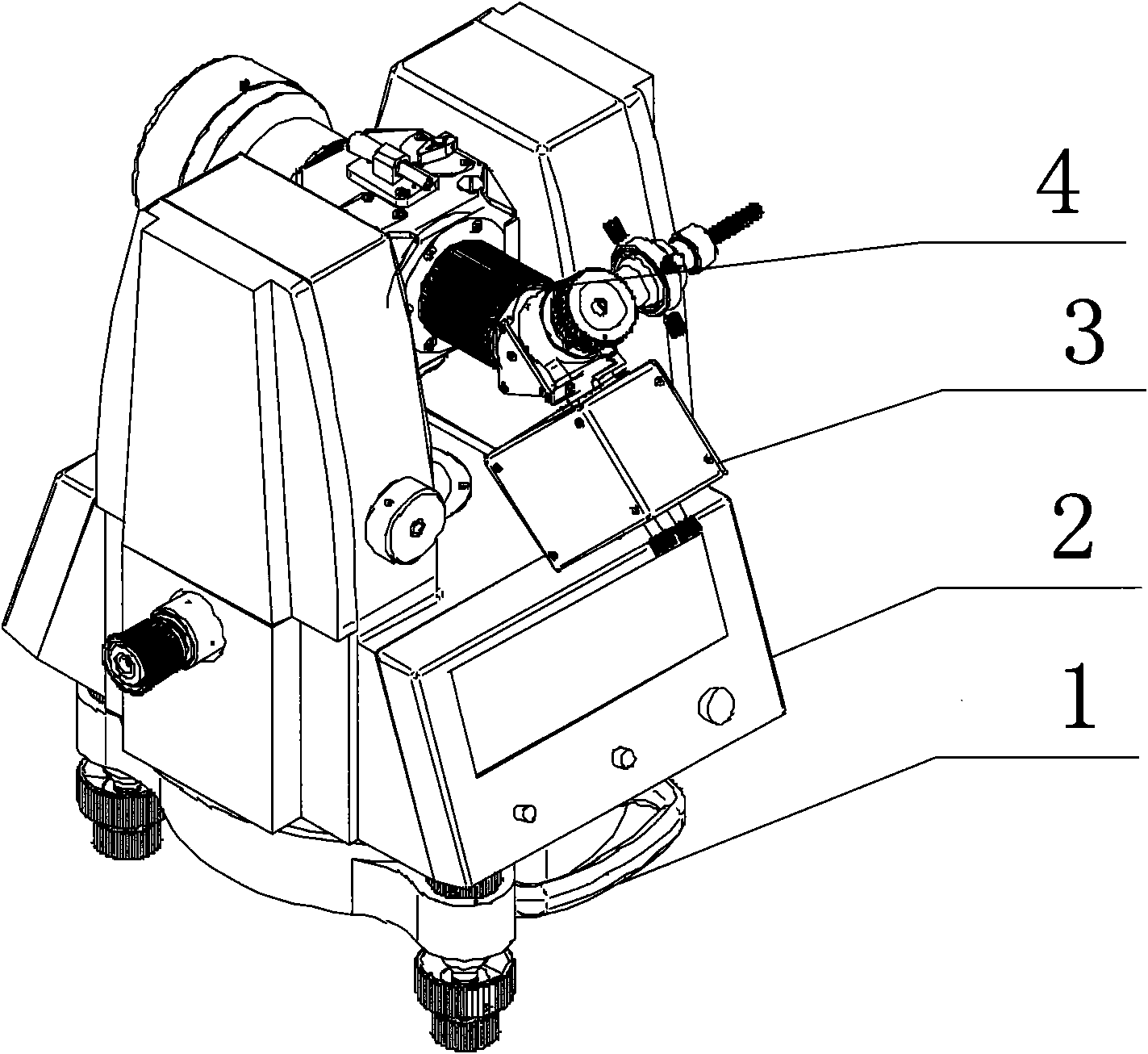
[0028] The invention mainly solves the initial azimuth measurement of a new generation carrier rocket based on the strapdown inertial group, and the strapdown inertial group tracking under the condition of rocket deformation or wind swing, and can realize the remote control aiming of the rocket with the cooperation of other single machines of the aiming system. The new generation of launch vehicles requires ground aiming to have collimation measurement capabilities. When the launch pad and the prism cannot be rotated, the collimator is used to capture and measure the angle between the normal of the prism and the known reference, and the measurement results are sent to the outside world through the network. At the same time, it is required that the ground aiming has the ability of unattended remote control aiming in the aiming room. The invention proposes a technical realization approach of an active two-dimensional tracking and collimating instrument, which is matched with a ne...


PUM

PropertyMeasurementUnit
Thicknessaaaaaaaaaa

Abstract

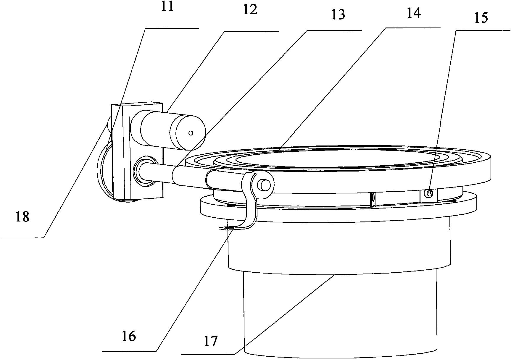
The invention relates to an active two-dimensional tracking collimator. The collimator consists of a base, a body frame, a telescope system, an electric control system, a visual image acquisition mechanism, a direction driving mechanism and a pitching driving mechanism, wherein the electric control system, the direction driving mechanism and the pitching driving mechanism are arranged in the body frame; the visual image acquisition mechanism is fixedly arranged on the telescope system; the telescope system is fixedly arranged on the upper part of the outer side of the body frame; and the electric control system is connected with the visual image acquisition mechanism, the direction driving mechanism and the pitching driving mechanism through data lines. The direction driving mechanism and the pitching driving mechanism realize two-dimensional (direction and pitching) movement of the collimator and the electric control system and the visual image acquisition mechanism realize two-dimensional (direction and pitching) information recognition of the collimator. In the telescope system of the invention, a normal of a target prism and a collimation deviation angle of an optical axis of the collimator are measured and subdivided by adopting a position sensitive device (PSD), so that the direction of the prism can be actively tracked and measured in real time.

Description

technical field [0001] The invention relates to a collimator, in particular to an active two-dimensional tracking, which belongs to the technical field of photoelectric measurement. Background technique [0002] The collimator currently used in the ground aiming system of the launch vehicle works by operating on-site by the operator to realize the long-distance photoelectric collimation of the prism of the rocket platform. dimensional (azimuth and pitch) tracking targeting capability and rocket targeting capability under wind swing. At the same time, the photoelectric collimation system of the collimator uses silicon photocells as the photosensitive device, and does not have the ability to measure the collimation deviation angle. Therefore, the collimator in active service can only perform collimation calibration on the rocket platform prism through the method of changing. [0003] However, the movable launch platform of the new generation of launch vehicles does not have t...

Claims


Application Information

Patent Timeline
IPC IPC(8): G02B23/16G01B11/26
Inventor 贺长水孙宝林丁爽任建国姜华高明杰宋小艳
Owner BEIJING INST OF SPACE LAUNCH TECH
Why Eureka
Eureka Blog
Learn More