
Remote automatic control adjustable-speed disc magnetic coupling

A magnetic coupling and coupling technology, applied in the direction of electric components, electromechanical transmissions, electrical components, etc., can solve the problems of motor heating and failure, reduce loss, improve precision, avoid restoring force and torque and The effect of vibration

Inactive Publication Date: 2010-12-15
JIANGSU UNIV
View PDF2 Cites 25 Cited by
  • Summary
  • Abstract
  • Description
  • Claims
  • Application Information

AI Technical Summary

Problems solved by technology

[0006] The purpose of the present invention is to provide a new type of remote automatic control adjustable speed disc magnetic coupling, improve the transmission efficiency of the magnetic coupling, and at the same time solve the problem of motor heating and even failure due to excessive induction current when the motor load is started

Method used


Image

  • Remote automatic control adjustable-speed disc magnetic coupling
  • Remote automatic control adjustable-speed disc magnetic coupling
  • Remote automatic control adjustable-speed disc magnetic coupling

Examples


Embodiment 2

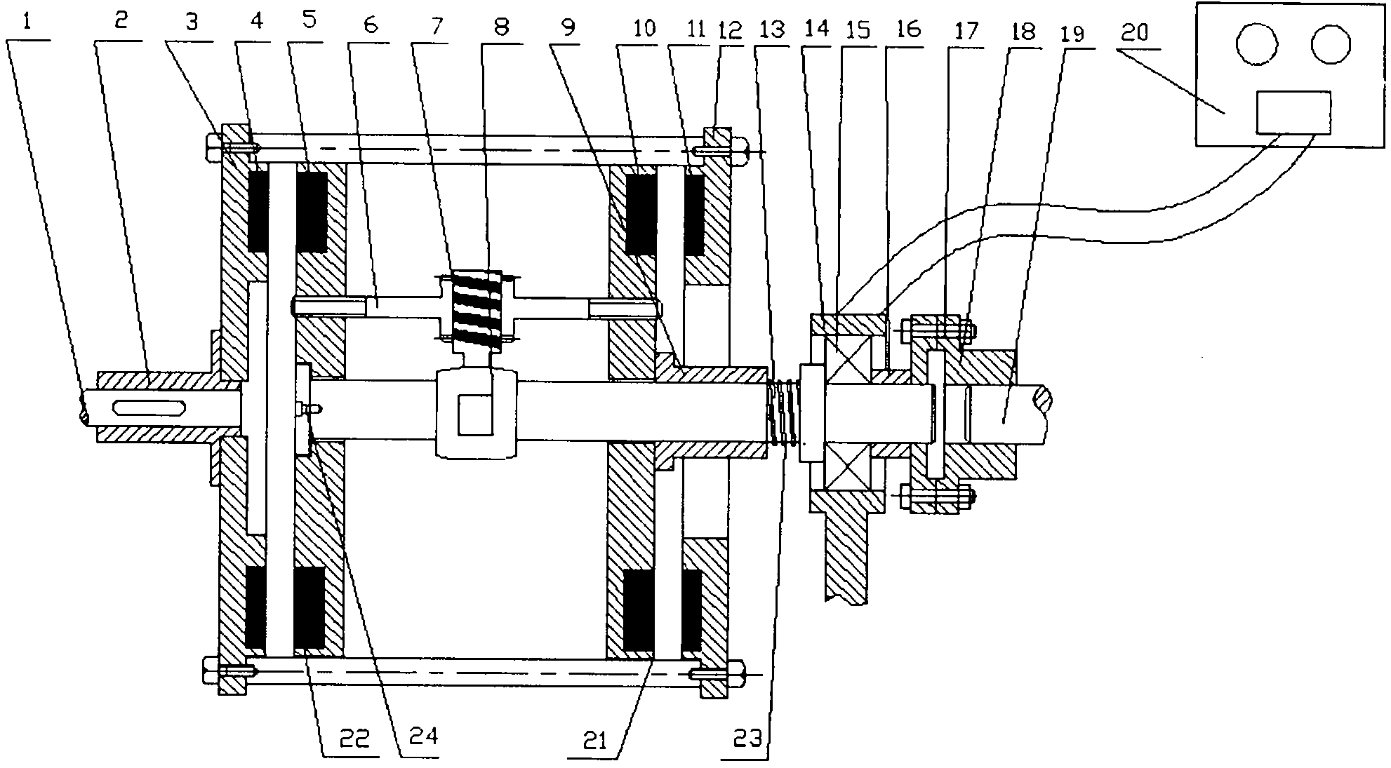
[0030] Embodiment 2: On the basis of Embodiment 1, a rotational speed or torque sensor can be added to the drive shaft 1 and output shaft 19 of the adjustable-speed magnetic induction coupling to sample the drive shaft 1 and output shaft 19 of the magnetic coupling in real time Speed ​​or torque signal, and send the signal to the central control unit in the speed controller. After the central control unit analyzes and processes these signals, it sends an instruction to control the forward or reverse rotation of the micro motor through the speed controller 20, so that The speed difference between the main and driven discs is within the specified range. The rotational speed difference requirement between the main and driven discs can be set in the speed controller.


PUM


Abstract

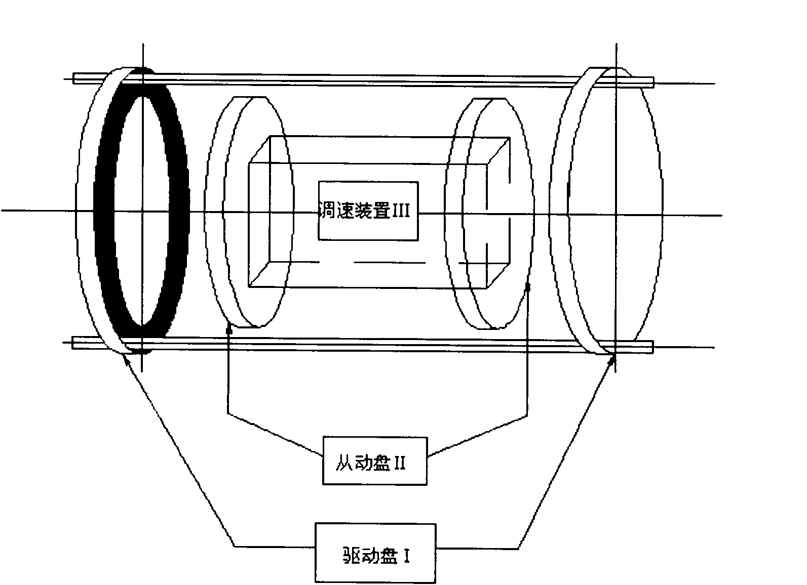
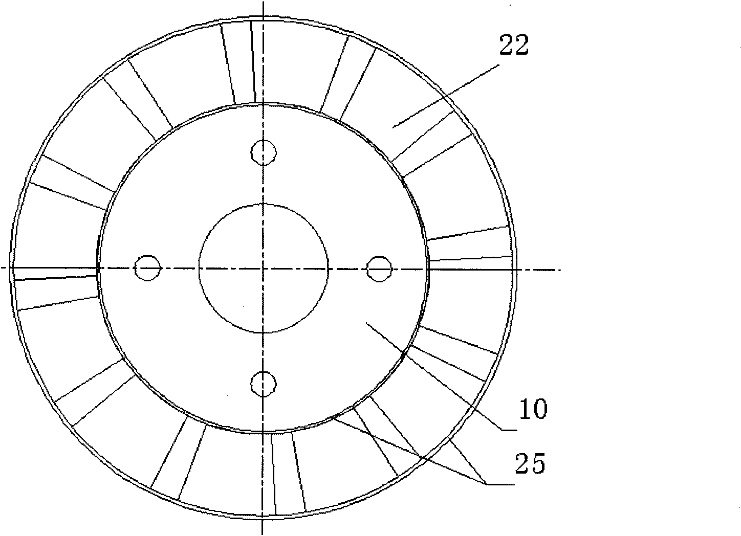
The invention discloses a remote automatic control adjustable-speed disc magnetic coupling, and relates to the technical field of transmission in mechanical engineering. The magnetic coupling consists of a driving disc assembly, a driven disc assembly and a speed regulation device assembly, and is characterized in that: the speed regulation device consists of a micro motor, a speed reducing mechanism, a double threaded screw rod and a speed controller; the micro motor is arranged on a driven shaft of the driven disc assembly of the magnetic coupling; the speed reducing mechanism is arranged on an output shaft of the micro motor; the speed controller controls the micro motor to rotate and drives the double threaded screw rod to rotate through the speed reducing mechanism; and left and right ends of the double threaded screw rod are in threaded connection with a left driven disc substrate and a right driven disc substrate of the driven disc assembly respectively. The rotating directions of threads at the two ends of the double threaded screw rod are opposite, when the double threaded screw rod rotates around the axis thereof, the left driven disc substrate and the right driven disc substrate of the driven disc assembly move close to or away from each other along the driven shaft of the magnetic coupling, so that air gaps among two groups of driven discs and driving discs are changed at the same time.

Description

technical field [0001] The invention relates to the technical field of transmission in mechanical engineering, and is a non-contact coupling magnetic coupling that can be remotely and automatically controlled. It is applied to the power transmission between a large vibration motor and a load and the transmission system of other devices. Background technique [0002] In the field of mechanical engineering, the coupling is an important part of the mechanical transmission system. It is called one of the three major devices in the mechanical transmission. It is widely used in various fields of the mechanical industry and is widely used in mines, Metallurgy, aviation, weapons, hydropower, chemical industry, textile and transportation sectors. Since the mechanical coupling is a rigid connection and mechanical force transmits torque, the axial offset will generate restoring force and moment during installation, and these forces and moments increase the load on adjacent components (...

Claims


Application Information

Patent Timeline
IPC IPC(8): H02K51/00
Inventor 杨超君倪志江蒋生发
Owner JIANGSU UNIV
Learn More