Method and device for calibrating acceleration and force sensors

A force sensor and sensor technology, applied in the testing/calibration of speed/acceleration/shock measurement equipment, speed/acceleration/shock measurement, measuring devices, etc., can solve problems such as limitations and reproducible wear

Inactive Publication Date: 2010-12-15
SPEKTRA SCHWINGUNGSTECHN & AKUSTIK DRESDEN
View PDF2 Cites 14 Cited by
  • Summary
  • Abstract
  • Description
  • Claims
  • Application Information

AI Technical Summary

Problems solved by technology

[0010] - The reproducibility of these acceleration signals and thus the calibration results is limited by the wear of these impact fittings

Method used


Image

  • Method and device for calibrating acceleration and force sensors
  • Method and device for calibrating acceleration and force sensors
  • Method and device for calibrating acceleration and force sensors

Examples


Embodiment Construction

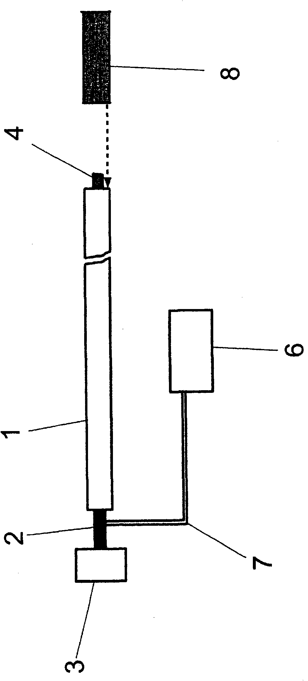
[0036] figure 1 A device for calibrating an acceleration sensor is shown. The device comprises a Hopkinson rod 1 in the form of a metal cylindrical rod having a length of 2 meters and a diameter of 20 mm. A piezo actuator 2 is connected by positive fit to the left-hand origin of the upper stem of the Hopkinson rod 1 . A cylindrical metal balance weight 3 with a diameter of 50 mm and a length of 30 mm is adhesively bonded to the actuator 2 . The sensor 4 to be calibrated is mounted at the right-hand end of the rod. The reference sensor system 8 is in the form of a laser. The open-loop and closed-loop control electronics control the piezoelectric actuator 2 via a control line 7 .

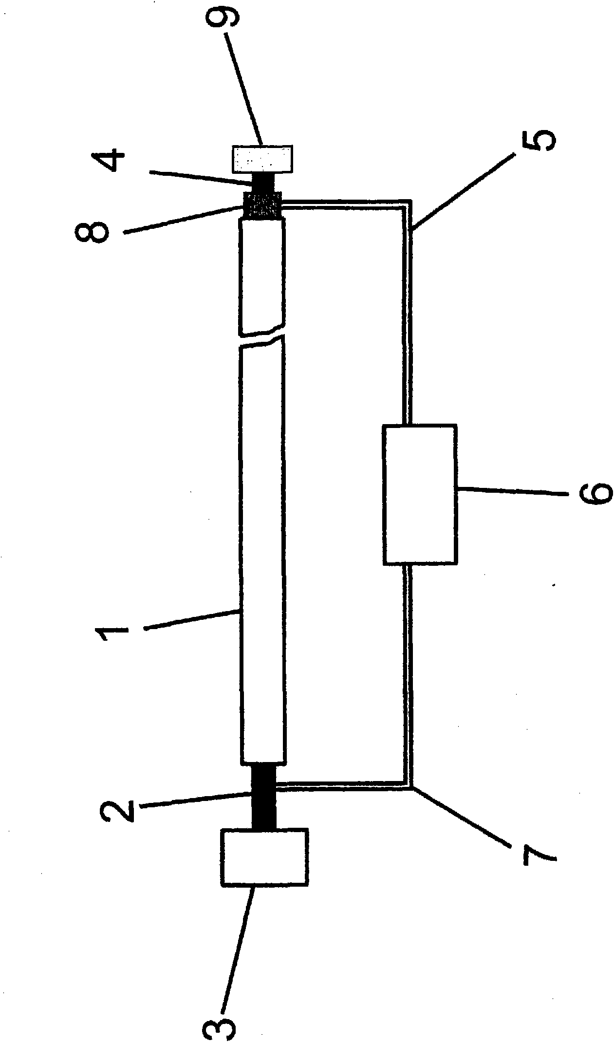
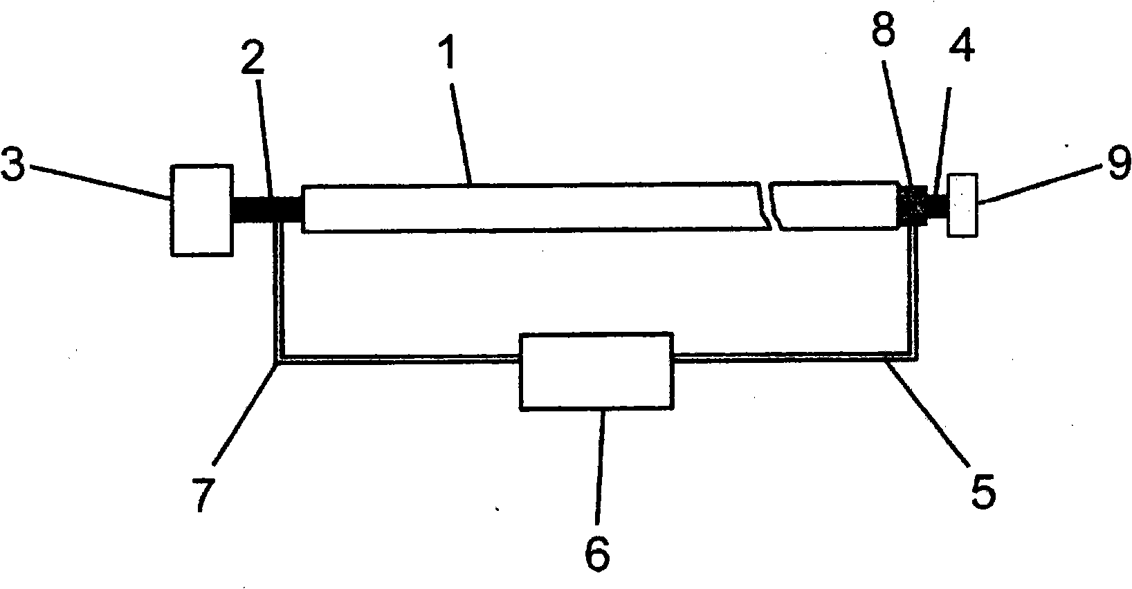
[0037] figure 2A device for calibrating a force sensor is described. The device comprises a Hopkinson rod 1, generally in the form of a metal cylindrical rod, having a length of 2 meters and a diameter of 20 mm. A piezo actuator 2 is connected by positive fit to the left-hand origin of the upp...


PUM

PropertyMeasurementUnit
lengthaaaaaaaaaa
thicknessaaaaaaaaaa
diameteraaaaaaaaaa

Abstract

The stimulation of waves in bars, in particular at high amplitudes, is used for the calibration of acceleration and force sensors. The invention relates to a method and a device for calibrating acceleration and force sensors by means of a Hopkinson bar for controlled influencing of the signal form the signal amplitude and the pulse duration of the signals over a large amplitude range. A reference sensor and the sensor for calibration are arranged on the Hopkinson bar. At the end of the Hopkinson bar opposite the sensors the stimulation is carried out by means of an electromechanical actuator for converting an electrical signal into a mechanical force. The electromechanical actuator may be controlled by a control and regulation electronic circuit. A targeted influence and change in the acceleration and force pulse form can be achieved.

Description

technical field [0001] The invention relates to a method and a device for exciting waves, especially waves with high amplitude, in a rod for calibrating acceleration sensors and force sensors. A sensor like this is an electromechanical transducer that converts mechanically variable acceleration or force into an electrically measurable signal, such as charge or voltage. Calibration must be performed in order to determine the transfer function of this sensor. Background technique [0002] Different devices for calibrating acceleration sensors are known. ISO16063 describes various devices and methods for calibrating vibration and shock sensors. For calibration greater than 1000m / s 2 For an acceleration amplitude of 1, a signal in the form of a shock must be used, that is to say a signal limited in time. The generally known principle of hammer and anvil (which is based on two solid bodies striking each other) at up to 5000m / s 2 work satisfactorily on acceleration magnitudes...

Claims


Application Information

Patent Timeline
Patent Type & Authority Applications(China)
IPC IPC(8): G01P21/00G01N3/30G01L25/00
CPCG01L25/00G01P21/00
Inventor 马丁·布鲁克
Owner SPEKTRA SCHWINGUNGSTECHN & AKUSTIK DRESDEN
Why Eureka
Try Eureka