Electroplastic self-piercing riveting device

A self-piercing riveting and electroplastic technology, applied in the field of automobile manufacturing, can solve the problems of reducing the strength of rivets, the rigidity of equipment punching riveting ability, reducing the plastic deformation resistance of riveted advanced high-strength steel, and the radial cracks of joints. Plastic deformation capacity, improved connection quality, strong mechanical interlocking effect

Active Publication Date: 2010-12-22
SHANGHAI JIAO TONG UNIV +1
View PDF6 Cites 22 Cited by
  • Summary
  • Abstract
  • Description
  • Claims
  • Application Information

AI Technical Summary

Problems solved by technology

[0005] Aiming at the above-mentioned deficiencies in the prior art, the present invention provides an electroplastic self-piercing riveting device, which increases the ductility of brittle light alloy materials such as cast aluminum and magnesium alloys by introducing the electroplastic effect of metal materials, and solves the problem It solves the problem that radial cracks or even brittle cracks are likely to occur at the bottom of the joi...

Method used


Image

  • Electroplastic self-piercing riveting device
  • Electroplastic self-piercing riveting device
  • Electroplastic self-piercing riveting device

Examples


Embodiment 1

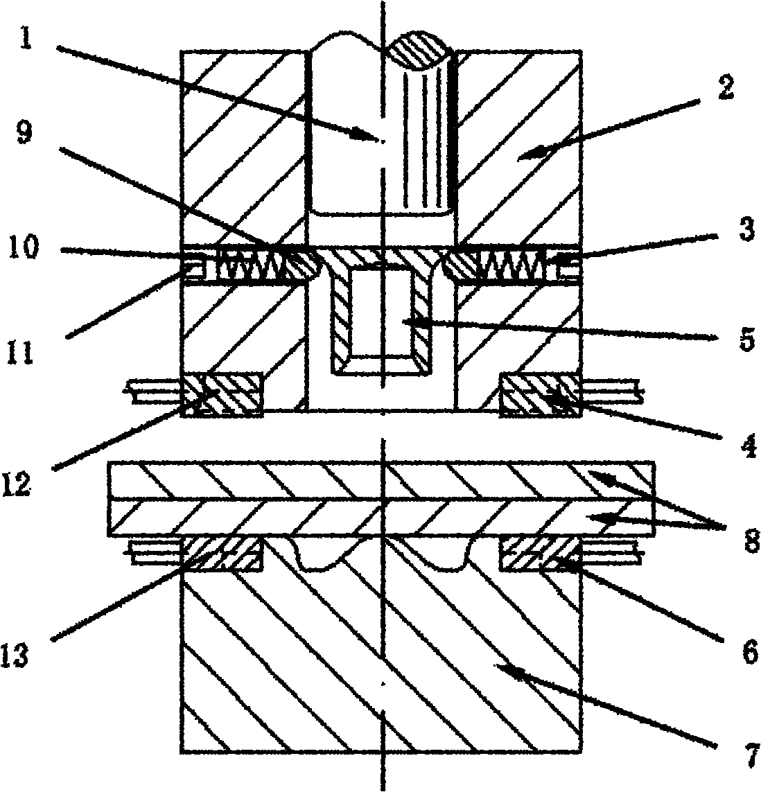
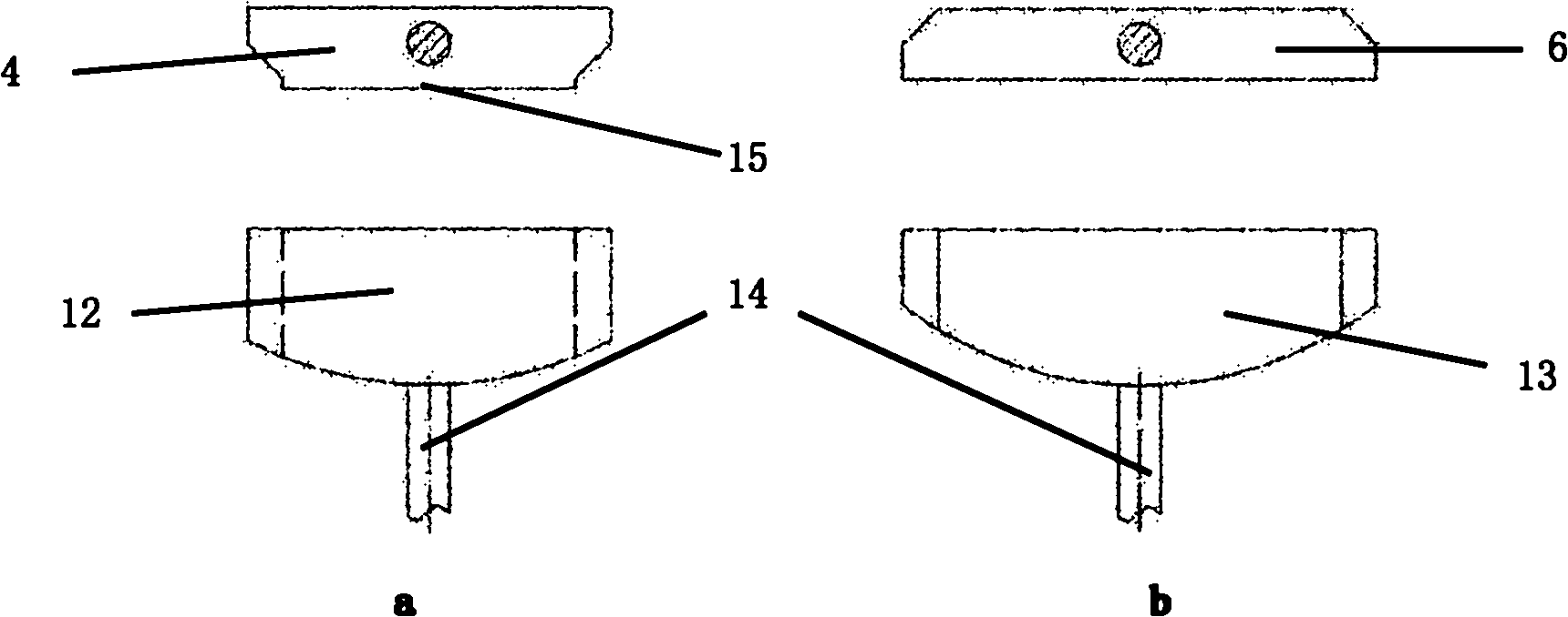
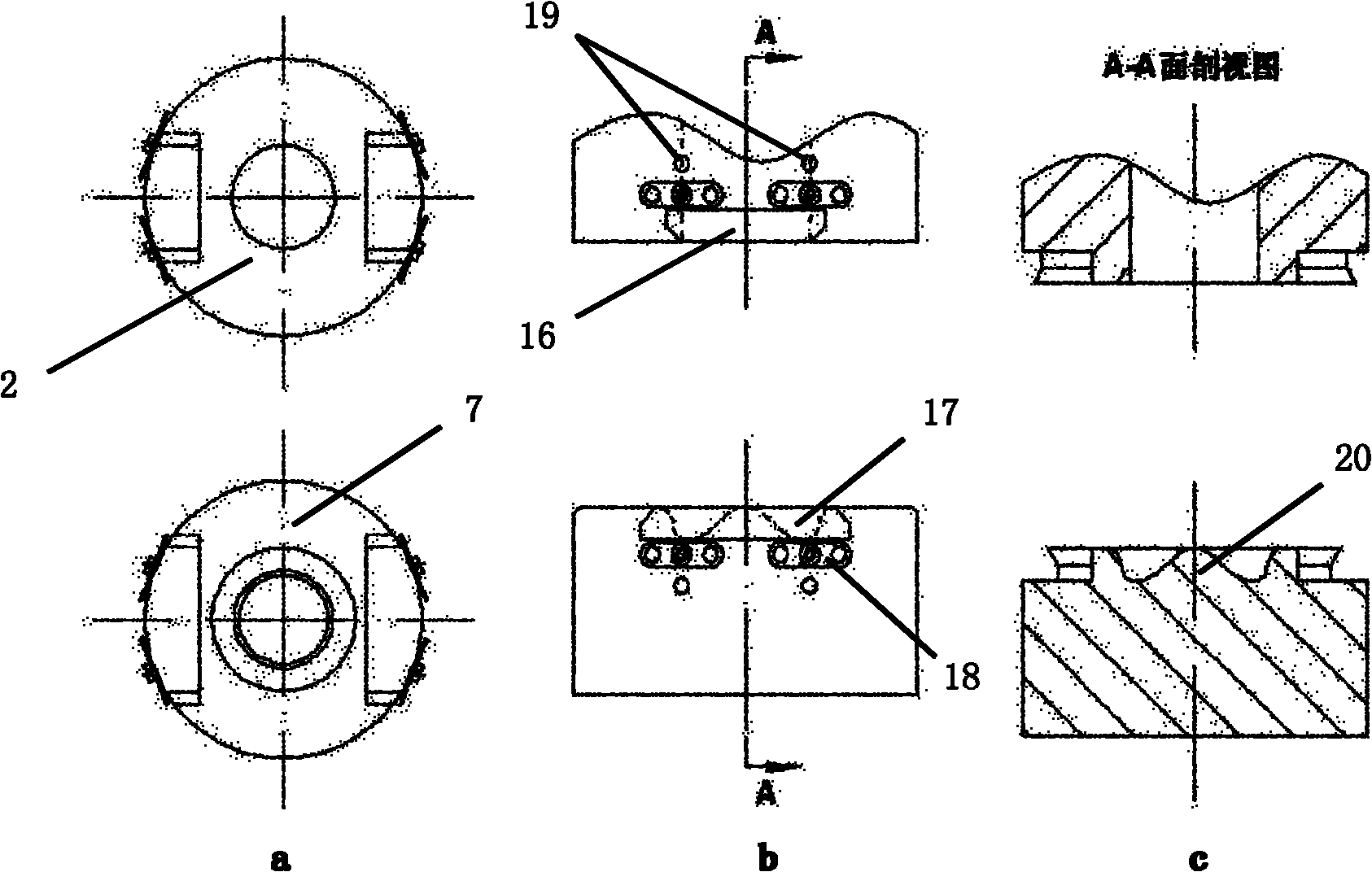
[0031] like figure 1 As shown, this embodiment includes: driving rod 1, blank holder ring 2, several spring bead positioning mechanisms 3, upper brush 4, semi-hollow rivet 5, lower brush 6 and die 7, wherein: blank holder ring 2 , The plates to be connected 8 and the die 7 are arranged sequentially from top to bottom, the driving rod 1 is sleeved in the blank holder 2, and several spring bead positioning mechanisms 3 are distributed horizontally in the radial direction in the blank holder 2, semi-hollow Rivet 5 is vertically placed in blankholder 2 and contacts with spring bead positioning mechanism 3, and drive rod 1, blankholder 2, semi-hollow rivet 5 and die 7 are coaxially arranged.

[0032] The driving rod 1 is made of insulating material or high-strength steel coated with insulating paint, and the diameter of the rod body is 7.8mm.

[0033] The inner diameter of the blank holder 2 is 8.2 mm, the outer diameter is 22 mm, and there are four threaded holes of φ2.4 evenly d...

Embodiment 2

[0052] The plates 8 to be connected in this embodiment are: aluminum alloy AA6061-T6+cast aluminum A356-T6, and the thickness of the plates matches: 1mm+3mm.

[0053] The semi-hollow rivet 5 in this embodiment adopts a traditional self-piercing riveting countersunk rivet with a head diameter of 7.8 mm, a leg outer diameter of 5.3 mm, and a rivet length of 7 mm. The material is boron-treated medium carbon steel.

[0054] Process parameters: the impact speed of the driving rod 1 is 100mm / in, the impact stroke is 7mm, the current of the upper brush 4 is 1800A, and the current of the lower brush 6 is 2400A.


PUM

PropertyMeasurementUnit
Diameteraaaaaaaaaa
The inside diameter ofaaaaaaaaaa
Outer diameteraaaaaaaaaa

Abstract

The invention relates to an electroplastic self-piercing riveting device belonging to the technical field of automobile manufacture. The device comprises a driving rod, a blank holder, a plurality of spring bead positioning mechanisms, four electric brushes in two groups, semitubular rivets and a female die, wherein the blank holder, a plate to be connected and the female die are sequentially arranged from top to bottom; the driving rod is sleeved in the blank holder; the plurality of spring bead positioning mechanisms are horizontally distributed in the blank holder along the radial direction; the semitubular rivets are vertically arranged in the blank holder and are in contact with the spring bead positioning mechanisms; the driving rod, the blank holder, the semitubular rivets and the female die are coaxially arranged; two upper electric brushes are respectively arranged at the bottom of the blank holder; and two lower electric brushes are oppositely arranged at the top of the female die. The invention solves the problem that when an alloy plate is riveted, the bottom of a joint generates radial cracks easily and even generates brittle rupture; and the invention reduces the plastic deformation resistance when the advanced high strength steel is riveted, and improves the comprehensive connection quality of joints.

Description

technical field [0001] The invention relates to a device in the technical field of automobile manufacturing, in particular to an electroplastic self-piercing riveting device. Background technique [0002] With the development of the automobile industry, the environmental protection performance and fuel economy of vehicles have increasingly become the main aspects of fierce competition among major automobile manufacturers. The above competition directly promotes the development of lightweight automobile bodies. Lightweight alloy materials such as magnesium and aluminum are gradually used in the manufacture of body structures due to their low density and high specific strength; at the same time, advanced high-strength steel has excellent comprehensive mechanical properties, and it will still occupy a place in future body manufacturing. Resistance spot welding is the most important connection method in traditional steel automobile body assembly. However, for the connection of l...

Claims


Application Information

Patent Timeline
IPC IPC(8): B21J15/10B21J15/38
CPCB21J15/025B21J15/08
Inventor 林忠钦李永兵楼铭来新民陈关龙王培中
Owner SHANGHAI JIAO TONG UNIV
Why Eureka
Try Eureka