[0013] The present invention will be described in more detail below in conjunction with the accompanying drawings.
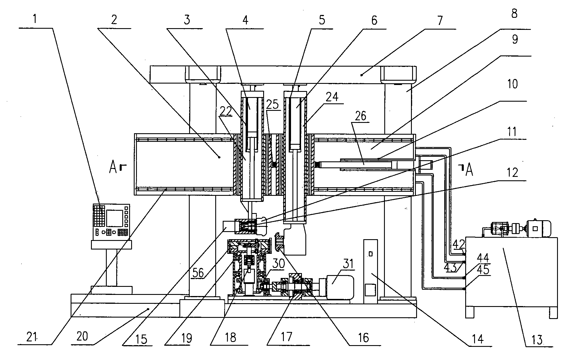
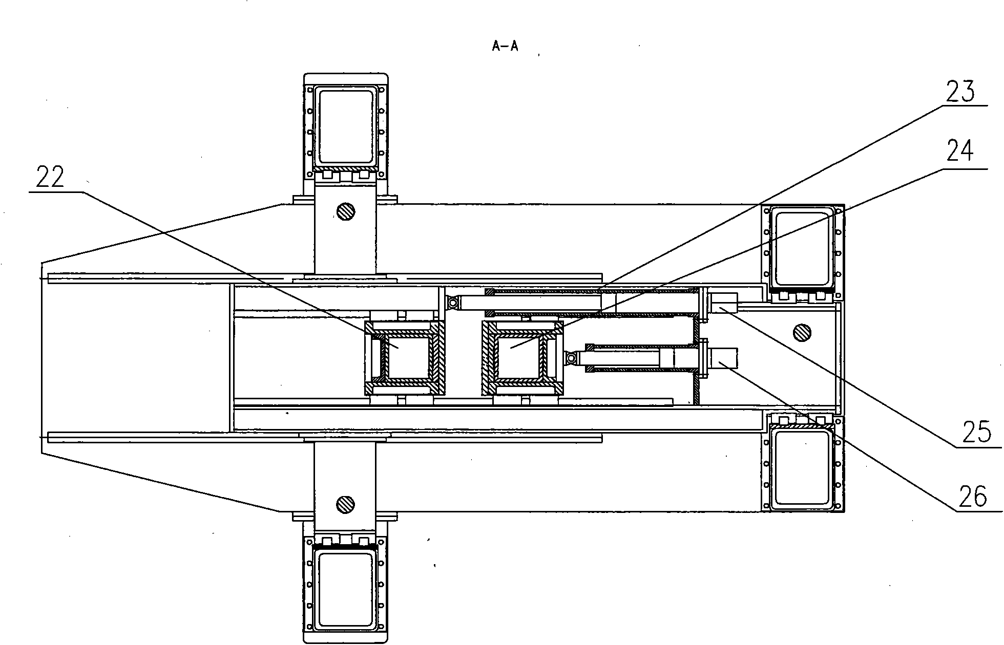
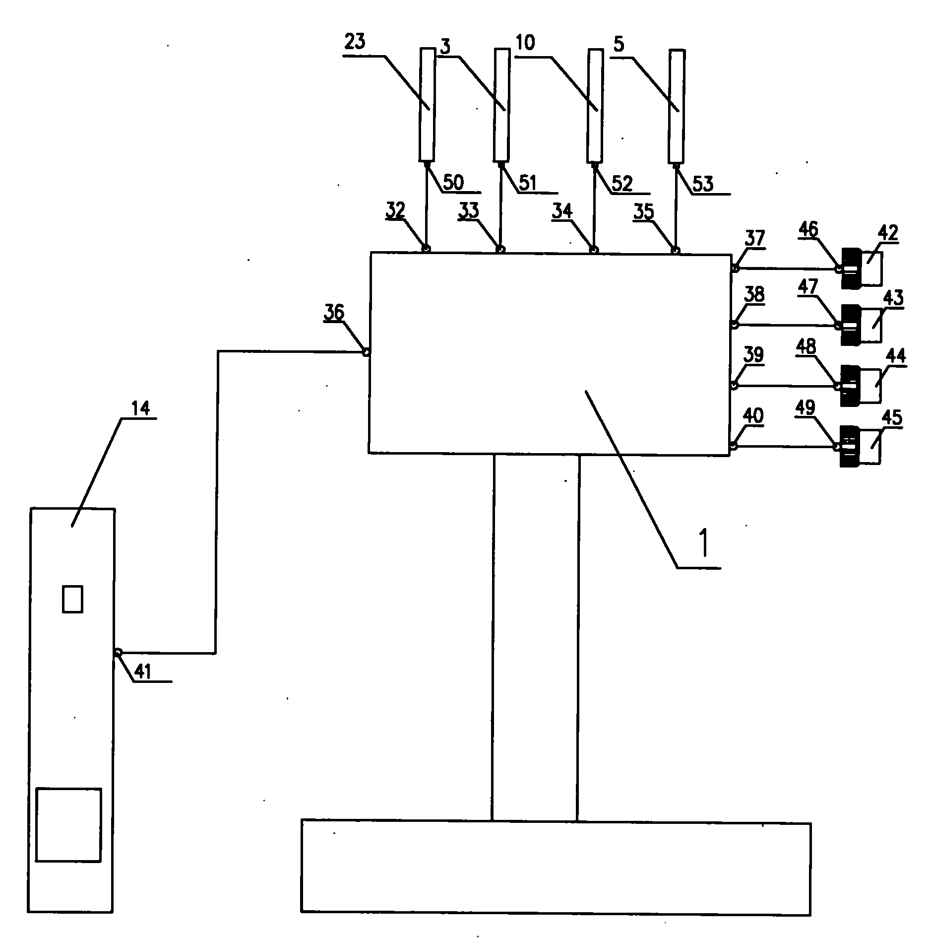
[0014] like figure 1 , figure 2 and image 3 As shown, the CNC moldless fan special spinning machine includes a CNC system 1 and a base 20 on which a vertically upward main shaft 18 is fixed, the upper part of the main shaft 18 and the expansion clamping device arranged on the base 20 The rotating head 56 of 19 is connected, the bottom of the main shaft 18 is connected with the main shaft motor 31 that is arranged on the base 20 through the steering structure 30, the motor shaft of the main shaft motor 31 is provided with an overrunning clutch 17, the power interface of the main shaft motor 31 and the frequency conversion The power output ports of the device 14 are connected, and the base 20 is also fixed with two vertically upward columns 8, the tops of the two columns 8 are connected with the machine top 7, and the first laterally moving brackets 2 are respectively arranged on the two columns 8 And the second laterally movable support 9, a section of guide rail 21 with a slide block is respectively set on the first laterally movable support 2 and the second laterally movable support 9, the slide block of the first laterally movable support 2 and the second laterally movable support 9 The slide block is respectively connected with the horizontal piston rod end of the first hydraulic servo cylinder 25 and the horizontal piston rod end of the second hydraulic servo cylinder 26, on the slide block of the first lateral movement support 2 and the second lateral movement support 9 A first vertically movable support 22 and a second longitudinally movable support 24 that can move longitudinally are arranged on the slide block respectively, and the bottom end of the first longitudinally movable support 22 is connected with the hydraulic motor 15, and the rotating shaft of the hydraulic motor 15 and the rotating shaft The pressure rollers 11 are connected by an overrunning clutch 12, and the bottom end of the second longitudinal movement support 24 is connected with the support wheel 16. The first longitudinal movement support 22 and the second longitudinal movement support 24 are respectively connected with the vertical piston rod of the third hydraulic servo cylinder 4. The end is connected with the vertical piston rod end of the fourth hydraulic servo cylinder 6, the first lateral movement support 2, the machine top 7 are close to the position of the first longitudinal movement support 22, the second transverse movement support 9 and the machine top 7 are close to the first The positions of the two longitudinally moving brackets 24 are respectively fixed with the reading head of the first grating ruler 23, the reading head of the second grating ruler 3, the reading head of the third grating ruler 10, and the reading head of the fourth grating ruler 5. The moving support 2, the first longitudinal moving support 22, the second lateral moving support 9 and the second longitudinal moving support 24 are respectively connected with the main ruler of the first grating ruler 23, the main ruler of the second grating ruler 3 and the third grating ruler 10. The main scale and the main scale of the fourth grating scale 5 are fixed, the signal port 50 of the first grating scale 23, the signal port 51 of the second grating scale 3, the signal port 52 of the third grating scale 10 and the signal port of the fourth grating scale 5 The signal ports 53 are respectively connected with the first data input port 32, the second data input port 33, the third data input port 34 and the fourth data input port 35 of the numerical control system 1 arranged on the base 20, the numerical control system The first control port 36, the second control port 37, the third control port 38, the fourth control port 39 and the fifth control port 40 of 1 are respectively connected with the controlled port 41 of the frequency conversion device 14 and the first numerical control hydraulic servo valve 42. The terminal 46 of the servo motor, the terminal 47 of the servo motor of the second numerical control hydraulic servo valve 43, the servo motor of the third numerical control hydraulic servo valve 44 The terminal 48 is connected to the terminal 49 of the servo motor of the fourth numerically controlled hydraulic servo valve 45, one end of the first numerically controlled hydraulic servo valve 42, one end of the second numerically controlled hydraulic servo valve 43, and one end of the third numerically controlled hydraulic servo valve 44 And one end of the fourth numerically controlled hydraulic servo valve 45 communicates with the oil port of the hydraulic oil pump station 13, the other end of the first numerically controlled hydraulic servo valve 42, the other end of the second numerically controlled hydraulic servo valve 43, the third numerically controlled hydraulic servo valve 44 The other end of the other end and the other end of the fourth numerically controlled hydraulic servo valve 45 are respectively connected with the oil port of the first hydraulic servo cylinder 25, the oil port of the second hydraulic servo cylinder 26, the oil port of the third hydraulic servo cylinder 4 and the fourth hydraulic servo cylinder. The oil ports of the oil cylinders 6 are connected, and the numerical control system 1 has a spindle motor speed control module and a displacement control module.
[0015] The working principle of the present invention is: first Figure 4The fan part 55 shown is fixed by the expansion and clamping device 19, and then the numerical control system 1, the frequency conversion device 14, the hydraulic oil pump station 13 and the spinning wheel motor 15 are powered on, and in the numerical control system 1 through the first data input port 32 , the second data input port 33, the third data input port 34 and the fourth data input port 35 receive signals from the signal port 50 of the first grating ruler 23, the signal port 51 of the second grating ruler 3, and the third grating ruler 10 The port 52 and the signal port 53 of the fourth grating scale 5 respectively return the position information, and these position information correspond to the first lateral movement support 2, the first longitudinal movement support 22, the second transverse movement support 9 and the second longitudinal movement respectively. The position information of the support 24, then through the input device of the numerical control system 1 to set the rotating speed required by the spindle motor speed control module and the displacement control module respectively and the parameters required by the displacement control module, start the spindle motor speed control module and the displacement control module after the input is completed The displacement control module starts the hydraulic motor 15 to drive the spinning wheel 11 to rotate at the same time, and the spindle motor speed control module sends an operation control command to the controlled port 41 of the frequency conversion device 14 through the first control port 36 of the numerical control system 1 according to the input speed , then the frequency conversion device 14 starts the main shaft motor 31 and drives the main shaft 18 to rotate, and the upper part of the rotating main shaft 18 drives the expansion clamping device 19 to rotate with the fan part 55 according to the set speed, and the displacement control module combines the required parameters with the return The returned position information is sent to the terminal 46 of the servo motor of the first numerical control hydraulic servo valve 42, the first control port 40 respectively through the second control port 37, the third control port 38, the fourth control port 39 and the fifth control port 40 of the numerical control system 1. The terminal 47 of the servomotor of two numerically controlled hydraulic servo valves 43, the terminal 48 of the servomotor of the third numerically controlled hydraulic servovalve 44 and the terminal 49 of the servomotor of the fourth numerically controlled hydraulic servovalve 45 send movement instructions, in movement instruction Under the drive of the first numerical control hydraulic servo valve 42, the second numerical control hydraulic servo valve 43, the third numerical control hydraulic servo valve 44 and the fourth numerical control hydraulic servo valve 45, the oil supplied to the first hydraulic servo cylinder 25 by the hydraulic oil pump station 13 is respectively port, the oil port of the second hydraulic servo cylinder 26, the oil port of the third hydraulic servo cylinder 4, and the oil port of the fourth hydraulic servo cylinder 6 respectively carry out whether to open the valve conduction oil supply and the continuity of the oil supply under the drive of the movement command. The operation of time, can make the piston rod of the first hydraulic servo cylinder 25, the piston rod of the second hydraulic servo cylinder 26, the piston rod of the 3rd hydraulic servo cylinder 4 and the piston rod of the 4th hydraulic servo cylinder 6 push respectively The slide block of the first lateral movement support 2, the slide block of the second transverse movement support 9, the first longitudinal movement support 22 and the second longitudinal movement support 24 carry out the linkage of four supports, thereby just can as Figure 4 As shown, when the main shaft 18 rotates to drive the expansion clamping device 19 and the fan part 55 to rotate, the spinning wheel 11 rotates and enters the rotating fan part 55 driven by the first laterally moving bracket 2 and the first longitudinally moving bracket 22 And contact, and under the drive of the second laterally moving bracket 9 and the second longitudinally moving bracket 24, the supporting wheel 16 also enters and contacts the rotating fan part 55, and rotates under the driving of the rotating fan part 55, the supporting wheel 16 And the spinning wheel 11 can complete the orderly extension of the crystal phase structure of the fan part 55 according to the trajectory set by the displacement control module, and complete the moldless automatic spinning process of the fan part 55 according to the designed curve. Through the use of hydraulic servo control technology and numerical control technology to precisely control the movement of the spinning wheel 11 and the supporting wheel 16 under the four-axis linkage, it can automatically complete various parts with a wall thickness greater than 12 mm or a diameter greater than 2000 mm without the need for molds. The automatic spin forming of fan parts has the characteristics of high product precision and high quality, and improves the production efficiency and product quality of fan parts, saves production costs and does not need to use molds in the production process. In addition, the motor shaft of the main shaft motor 31 is provided with an overrunning clutch 17, and an overrunning clutch 12 is provided between the rotating shaft of the hydraulic motor 15 and the spinning wheel 11, so that the gap between the spinning wheel 11 and the fan parts can be solved. The problem of synchronous rotation interference; The four grating scales of the first grating scale 23, the second grating scale 3, the third grating scale 10 and the fourth grating scale 5 can be replaced by four pull wire displacement sensors, so that Further cost savings can be achieved.