Method for welding steel plate by multi-layer welding

A technology for welding steel plates and multi-layer welding, which can be used in welding media, welding equipment, welding equipment, etc., and can solve problems such as insufficient mechanical properties of welded joints.

Inactive Publication Date: 2010-12-29
PANZHIHUA IRON & STEEL RES INST OF PANGANG GROUP +3
View PDF0 Cites 21 Cited by
  • Summary
  • Abstract
  • Description
  • Claims
  • Application Information

AI Technical Summary

Problems solved by technology

[0005] Therefore, in the prior art, when using multi-layer welding to weld steel plates, especially when welding steel plates with high alloy composition and high mechanical performance requirements, it is difficult to avoid t

Method used


Image

  • Method for welding steel plate by multi-layer welding
  • Method for welding steel plate by multi-layer welding
  • Method for welding steel plate by multi-layer welding

Examples


Embodiment 1

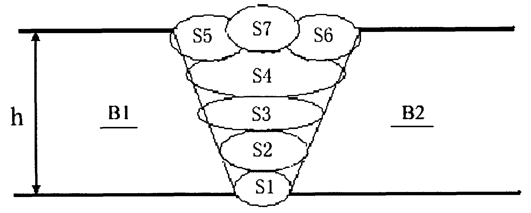
[0034] use figure 2 The multilayer welding process shown uses MAG welding to perform multilayer welding of Q450NQR1 steel plates with a thickness of 12mm. The shielding gas for MAG welding is Ar80%+20%CO 2 (volume fraction); the steel plate has a V-shaped groove; it is welded by one-sided welding and double-sided forming. The alloy composition of Q450NQR1 steel plate is shown in Table 1 (the content unit of each alloy element is weight %); S1-S7 uses the same welding material TH550-NQ-A, and the composition (mass %) is C 0.06, Si 0.37, Mn 1.30 , P 0.014, S 0.009, Cu 0.34, Cr 0.34, Ni 0.52, welding wire specification Φ1.2mm; the process parameters of MAG welding and the thickness of deposited metal in each pass are shown in Table 2. Among them, the interlayer temperature of S1-S6 welding is 100°C, and the interlayer temperature of S7 welding is 180°C. The groove angle of the V-shaped groove of two Q450NQR1 steel plates is 45°, and the pairing gap is 2.2mm.

[0035] Table 1 ...

Embodiment 2

[0041] The Q450NQR1 steel plate with a thickness of 12mm is welded according to the method of Example 1. The difference is that the alloy composition of the Q450NQR1 steel plate used is shown in Table 1, and the process parameters of MAG welding and the thickness of the deposited metal in each pass are shown in Table 3. It shows that the interlayer temperature of S1-S6 is 120°C, and the interlayer temperature of S7 welding is 190°C.

[0042] table 3

[0043] pass

Embodiment 3

[0045] The Q450NQR1 steel plate with a thickness of 12mm is welded according to the method of Example 2. The difference is that the alloy composition of the Q450NQR1 steel plate used is shown in Table 1, and the process parameters of MAG welding and the thickness of the deposited metal in each pass are shown in Table 4. It shows that the interlayer temperature of S1-S6 is 150°C, the interlayer temperature of S7 welding is 200°C, and the groove angle of the V-shaped groove of two Q450NQR1 steel plates is 60°.

[0046] Table 4

[0047] pass


PUM

PropertyMeasurementUnit
Thicknessaaaaaaaaaa
Thicknessaaaaaaaaaa
Thicknessaaaaaaaaaa

Abstract

The invention discloses a method for welding a steel plate by multi-layer welding. The method comprises priming welding, filling welding and cosmetic welding, wherein the cosmetic welding comprises the steps of respectively performing first pass welding and second pass welding on the surfaces of two steel plates to be welded so as to form a first-pass weld pass and a second-pass weld pass, then performing third pass welding on the first-pass weld pass and the second-pass weld pass to form a third-pass weld pass connecting the first-pass weld pass and the second-pass weld pass. The method for welding the steel plate by multi-layer welding can play the role of slowing down the cooling of the first-pass weld pass and the second-pass weld pass through the third-pass weld pass, and simultaneously, normalizing is carried out on welding points. After being austenitized, the steel plate tissues in a heat affected zone and a fusion zone slowly cool down, so that the welding points form pearlite tissues with fine pearlites, thereby improving the mechanical properties of the welding points such as toughness and the like.

Description

technical field [0001] The invention relates to a method for multilayer welding of steel plates. Background technique [0002] During welding, the high-temperature heat of the molten welding material is concentrated, so that the workpiece metal in contact with the welding material is melted and joined with the welding material in a molten state to form a weld seam and a welded joint. The whole welding joint is composed of weld seam, fusion zone and heat-affected zone. Among them, the weld is completely melted during welding; the heat-affected zone does not melt during welding; the fusion zone is the transition zone between the weld and the heat-affected zone (weld and heat-affected zone such as figure 1 shown). While the welding material and the base metal are combined in a molten state, the weld conducts heat to the workpiece metals (base metals) B1 and B2. This causes changes in the metal structure of the weld and heat-affected zone. Since each point on the weld seam a...

Claims


Application Information

Patent Timeline
IPC IPC(8): B23K9/173B23K9/095B23K35/38B23K33/00B23K9/025F16B5/08
Inventor 余腾义李大东李军朱宁黄渠龚洪君
Owner PANZHIHUA IRON & STEEL RES INST OF PANGANG GROUP
Why Eureka
Try Eureka