Method of making hollow concrete elements

A technology for concrete and components, used in the manufacture of tools, molds, supply devices, etc., to solve problems such as inefficiency, difficulty in detecting defects and inhomogeneity

Inactive Publication Date: 2010-12-29
TELEFON AB LM ERICSSON (PUBL)
View PDF5 Cites 6 Cited by
  • Summary
  • Abstract
  • Description
  • Claims
  • Application Information

AI Technical Summary

Problems solved by technology

[0007] Some of the problems with existing solutions and methods are that they are inef

Method used


Image

  • Method of making hollow concrete elements
  • Method of making hollow concrete elements
  • Method of making hollow concrete elements

Examples


Embodiment Construction

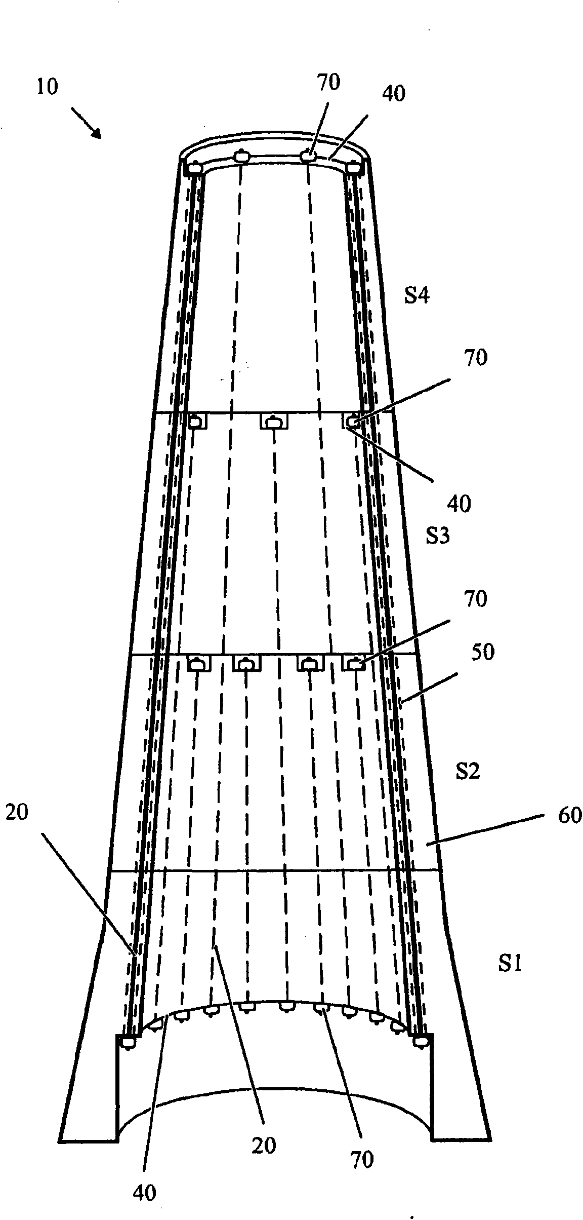
[0044] The present invention makes it possible to use prefabricated segmented elongated structures as an alternative to molded in situ structures or prefabricated integrally molded structures.

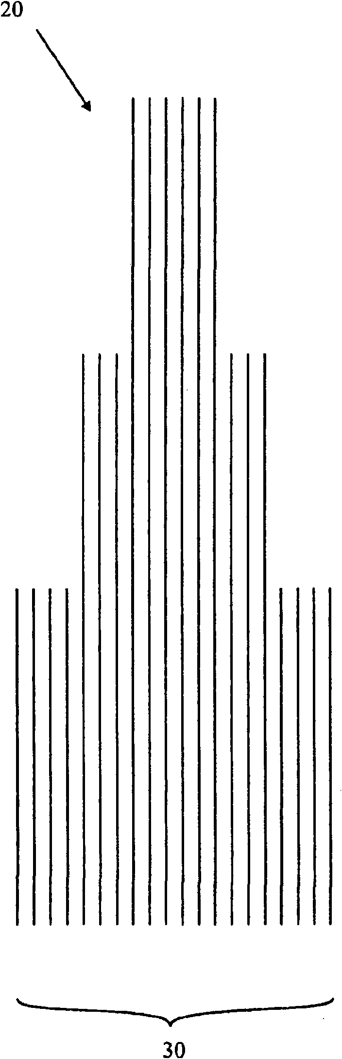
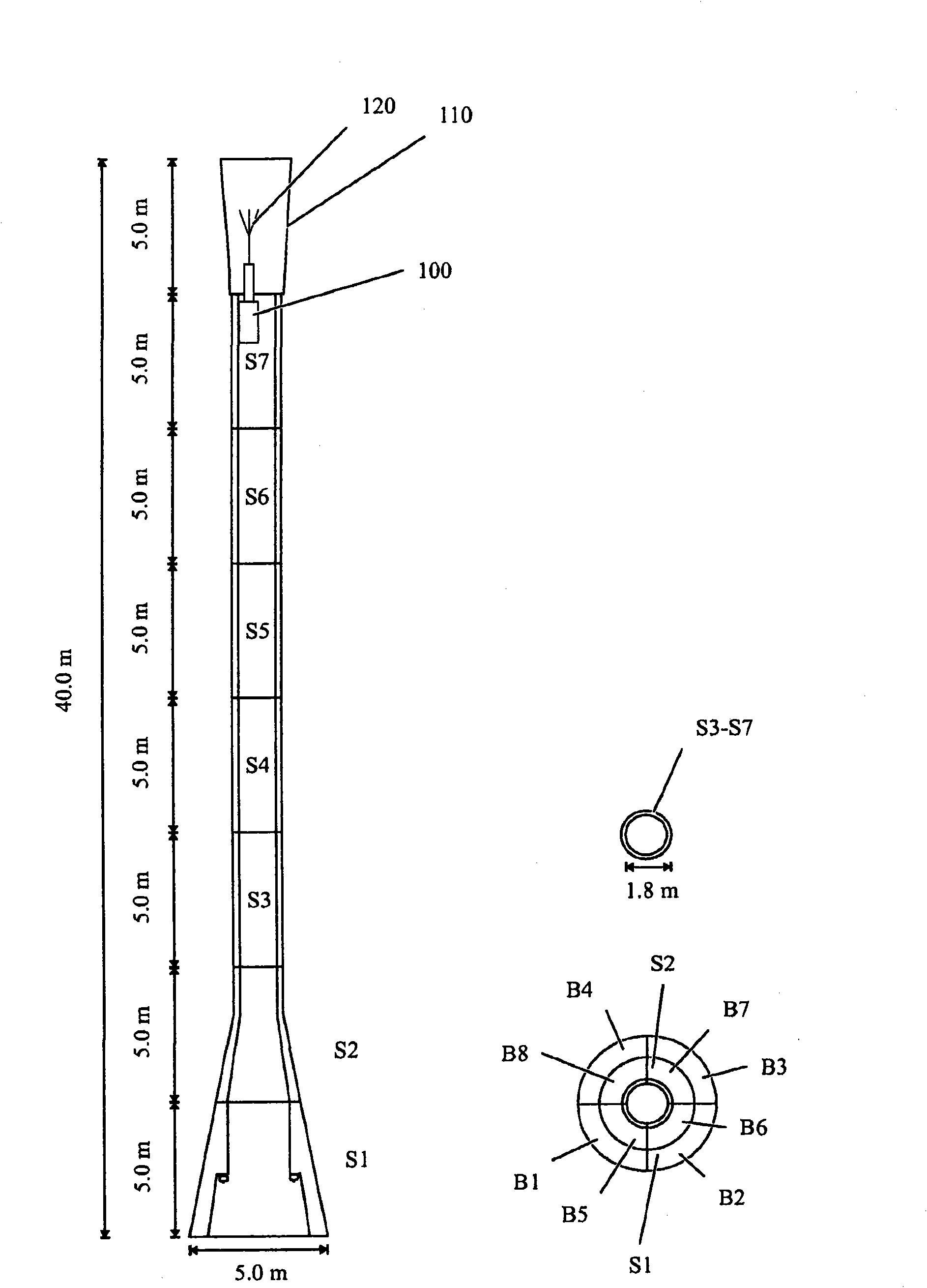
[0045] Figure 1a and 1b The elongated structure 10 along the longitudinal section S1-S4 is schematically shown. The elongated structure comprises: a base section S1; at least one intermediate section S2, S3; and a terminating section S4, wherein said sections are formed substantially of reinforced concrete. Segments S1-S4 are longitudinally interconnected by a plurality of elongate fastening members 20 which together form a longitudinally seamless longitudinal interconnection interconnecting base segment S1 to terminating segment S4. Even structure 30. In other words, it can be said that the plurality of elongate fastening members 20 together form a continuous longitudinal interconnection structure 30 throughout the segmented elongate structure 10 . As will be disclosed in more det...


PUM


Abstract

Method of making an open ended hollow concrete element (240) comprising the steps of arranging a mould (220) about an essentially horizontal roller shaft (210), the mould comprising a sleeve-shaped mould wall (230) defining the outer peripheral shape of the concrete element (240) and a first end rim (250) and a second end rim (260) each with an inner periphery (251, 261) smaller than the inner periphery of the mould wall (230) at respective end and defining the end surfaces of the concrete element. The mould (220) is rotatably supported by the roller shaft (210) by abutment at the inner peripheries of the first end rim (250) and the second end rim (260), so that the roller shaft (210) upon rotation defines the inner peripheral shape of the concrete elements (240); rotating the shaft to rotate the mould; feeding curable concrete to the rotating mold (220); stopping the rotation of the mould (220); removing the cured concrete element from the mould (220); w wherein the inner perimeter of the mould wall defines an exterior shape of the concrete element that varies along and/or radially to the direction of the rotational axis. There is further provided an arrangement (200) for making such concrete elements (240).

Description

technical field [0001] The present invention relates generally to concrete elements, and more particularly to methods and apparatus for manufacturing open-ended hollow concrete elements. Background technique [0002] Open-ended hollow concrete elements can be found in various implementations, primarily as buried pipes and sometimes as structural elements in buildings, bridges, towers, etc. [0003] In various fields, elongated reinforced concrete structures are frequently used. Examples of elongated reinforced concrete structures are different types of masts and towers, wire racks, chimneys, building structures, curved beams, etc. [0004] Traditionally, such elongated structures are injection molded in situ in a single molding step or through several subsequent molding steps in which previously molded stiffening elements are integrally formed to achieve a through-through structure Continuous longitudinal reinforcement structure. However, on-site molding is time-consuming...

Claims


Application Information

Patent Timeline
IPC IPC(8): B28B21/24B28B21/80E04H12/12
CPCE04H12/16B28B13/027B28B23/10B28B21/30E04H12/12
Inventor 彼得·哈格卢特福·埃
Owner TELEFON AB LM ERICSSON (PUBL)
Why Eureka
Try Eureka