
Positioning method of twin-lift spreader bridge crane based on image sensor

An image sensor and positioning method technology, applied in the direction of load hanging components, transportation and packaging, etc., can solve the problems of complicated use, inconvenient maintenance, poor anti-interference ability, etc., and achieve practical, effective, low cost, and convenient use effects

Inactive Publication Date: 2011-01-05
SHANGHAI MARITIME UNIVERSITY
View PDF4 Cites 29 Cited by
  • Summary
  • Abstract
  • Description
  • Claims
  • Application Information

AI Technical Summary

Problems solved by technology

In some recent reports, some institutions have carried out research and application on load anti-sway and load positioning control of single lifting bridge cranes. In these bridge crane control systems, more complex laser angle meters and angle sensors are generally used to detect The device realizes the detection of the load swing angle. These detection devices are only suitable for the detection of the load swing angle of the bridge crane with a single spreader, but they cannot detect the rope length of the spreader. Moreover, the detection device is expensive, complicated to use, poor in anti-interference ability, and difficult to maintain. It is also inconvenient, and some also have special requirements for the use environment (for example, the use of laser equipment for angle recognition requires a good working environment, dust-free, rain-free, and natural conditions such as shelter), which limit the swing angle of the above-mentioned bridge crane spreader Application of Angle Detection Device

Method used


Image

  • Positioning method of twin-lift spreader bridge crane based on image sensor
  • Positioning method of twin-lift spreader bridge crane based on image sensor

Examples


Embodiment Construction

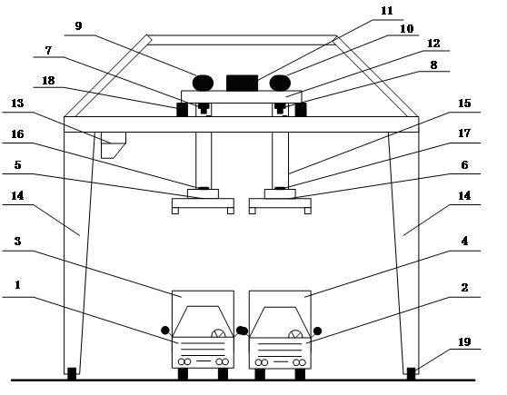
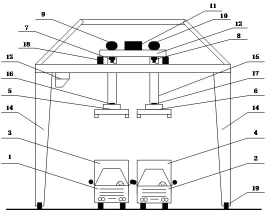
[0023] The specific working process of the bridge crane image detection and positioning system involved in the present invention is as follows: (see attached figure 1 )

[0024] The new double-lift double-spreader bridge crane can simultaneously load and unload two 40-foot containers or four 20-foot containers. The bridge crane is equipped with two independent spreaders 5 and 6, which can work simultaneously or separately; the two video cameras 7 and 8 installed directly under the bridge crane trolley 12 can respectively take pictures of the two spreaders 5 and 6 The operating conditions of the spreader, and the captured video image information is transmitted to the video image processors 9 and 10 corresponding to the cameras 7 and 8 for analysis and processing; the working images of the spreader captured by the cameras can be analyzed and processed in real time, and the crane can be extracted. position information of the spreader, and calculate the swing angle and swing ang...


PUM


Abstract

The invention relates to a positioning method of twin-lift spreader bridge crane based on an image sensor. Index points (16) and (17) are arranged on a twin-lift spreader, two independent video cameras (7) and (8) are used for respectively shooting swinging images of the twin-lift spreader, and video frames are transmitted to video image processors (9) and (10) corresponding to the video cameras; each video image processor comprises a CPU (Central Processing Unit), a video processing module, a memory, an I / O (Input / Output) unit, and the like, wherein the input end of each video image processor is connected with each video camera, and the output end of each video image processor is connected with a control computer (11); and swing-angle information and sling-length information of the twin-lift spreader are calculated through an image-position processing algorithm and an image-depth restoring algorithm and are transmitted to the control computer in real time in order to complete the anti-swing positioning control of a current control period. The positioning method is simple, has the advantages of low cost and convenient use and not only is used for the information feedback of a swing angle and a sling length of an anti-swing positioning control system of the twin-lift spreader bridge crane, but also is used for the hand operation reference of a crane driver.

Description

technical field [0001] The invention relates to the technical fields of information technology and bridge crane loading and unloading, in particular to a positioning detection method for a bridge crane with double spreaders. Background technique [0002] Double-lift double-sling bridge crane (including field crane and quay crane) is a new type of port container handling machinery. Because it has two lifting spreaders, it can work at the same time, thus greatly improving the efficiency of container loading and unloading. However, this double-lifting double-slinger bridge crane system has a complex structure and various working methods; since this new type of bridge crane has two spreaders that can be lifted independently, it brings great difficulty to the detection of the swing angle of the spreader. [0003] Existing bridge crane detection devices are all designed for single-sling bridge cranes, and they all use relatively complicated detection instruments for the detection ...

Claims


Application Information

Patent Timeline
IPC IPC(8): B66C13/04B66C13/06B66C13/16
Inventor 徐为民顾伟褚建新康伟沈爱弟
Owner SHANGHAI MARITIME UNIVERSITY
Learn More