Template with rigid-flexible composite structure and partition wall construction method by retaining roadway along goaf thereof

A structural formwork and rigid-flexible composite technology, which is applied in the direction of formwork/formwork/working frame, formwork/formwork components, earthwork drilling and mining, etc., can solve the problems of high construction cost, poor airtightness, and slow construction speed, and achieve Improved bearing capacity and anti-deformation capacity, improved stability, and fast construction speed

Inactive Publication Date: 2011-01-05
惠兴田
View PDF5 Cites 16 Cited by
  • Summary
  • Abstract
  • Description
  • Claims
  • Application Information

AI Technical Summary

Problems solved by technology

Low support strength of wooden stacks and dense pillars cannot meet the needs of most projects
Gangue bags and masonry walls cannot be connected to the roof, resulting in excessive sinking of the roof and poor support effect
The concrete diaphragm wall uses rigid formwork to support the formwork. The disadvantages of these methods are: it requires a lot of manpower and material resources to dry the sand and gravel and mix it with cement. After that, it is bagged and transported to the underground for water mixing again. The labor intensity is high and the construction speed is slow. ; The rigid formwork is not easy to change with the fluctuation of the top and bottom slabs, resulting in poor airtightness, easy grout leakage in the process of pouring concrete, and it is difficult for the poured concrete to be tightly combined with the coal seam roof
Although flexible formwork solves the problem of roof connection, it cannot solve the problem of wall forming and the construction cost is very high, and it cannot meet the construction needs of walls over 2 meters

Method used


Image

  • Template with rigid-flexible composite structure and partition wall construction method by retaining roadway along goaf thereof
  • Template with rigid-flexible composite structure and partition wall construction method by retaining roadway along goaf thereof
  • Template with rigid-flexible composite structure and partition wall construction method by retaining roadway along goaf thereof

Examples


Embodiment 1

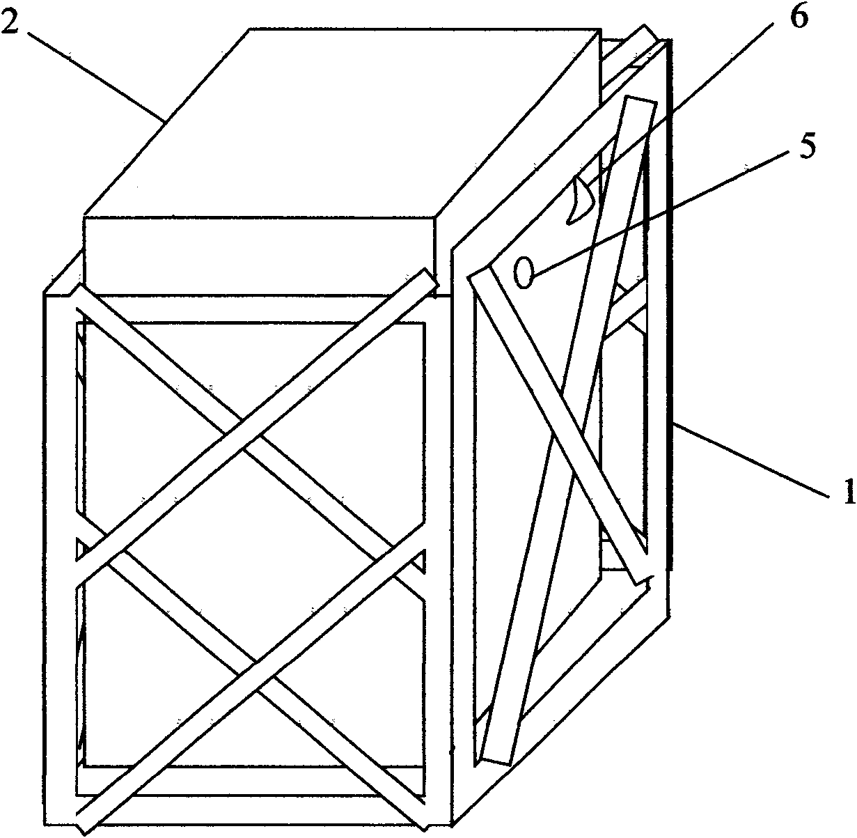
[0033] Such as figure 1 The rigid-flexible composite structure formwork shown is composed of two parts: the rigid outer formwork 1 of the outer layer and the flexible inner tire mold 2 arranged in the rigid outer formwork 1 .

[0034] The flexible inner tire mold 2 is a closed bag structure with an openable opening made of fiber cloth, and is provided with a grouting port 5 and a suspension buckle 6 .

[0035] The method of using the rigid-flexible composite structure template for concrete structure construction is carried out according to the following steps:

[0036] 1) fixing the flexible inner tube mold 2 on the top plate;

[0037] 2) fixing the rigid outer template 1;

[0038] 3) Connect the concrete pump to the grouting port 5;

[0039] 4) Pumping concrete;

[0040] 5) Remove the rigid outer template 1 after pumping for 3 hours.

Embodiment 2

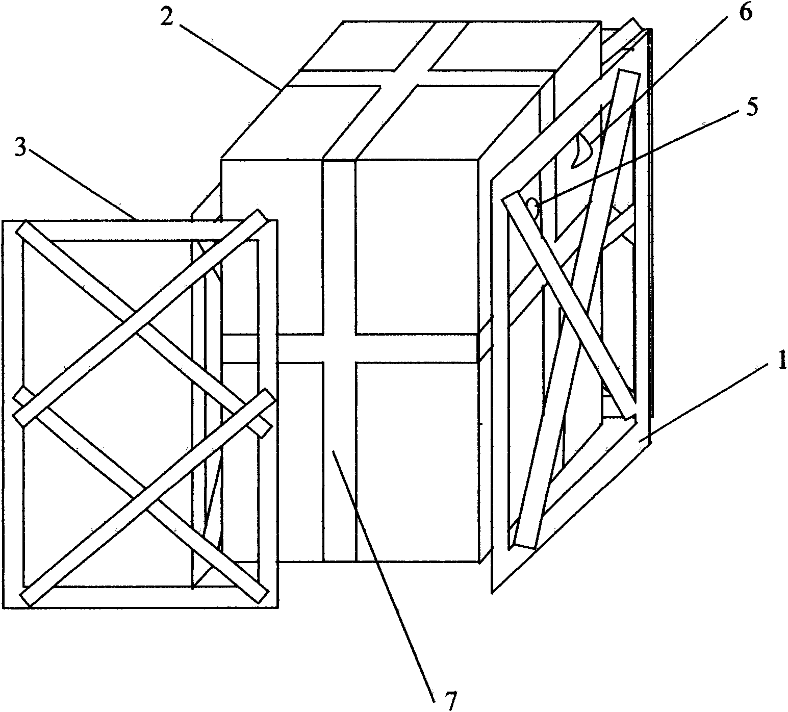
[0042] Such as figure 2 The rigid-flexible composite structure formwork shown is composed of two parts: the rigid outer formwork 1 of the outer layer and the flexible inner tire mold 2 arranged in the rigid outer formwork 1 . One side of the rigid outer template 1 is a slidable and fixed baffle plate 3 .

[0043] The flexible inner tube mold 2 is a closed bag structure, and the flexible inner tube mold 2 is a fiber cloth bag.

[0044] The flexible inner tire mold 2 is provided with an elastically deformable strip 7 adapted to the rigid outer template and the expansion top.

[0045] The method of using the rigid-flexible composite structure template for concrete structure construction is carried out according to the following steps:

[0046] 1) Fix the flexible inner tube mold 2 on the rigid outer template 1;

[0047] 2) Fix the baffle plate 3 of the rigid outer template 1;

[0048] 3) Connect the concrete pump to the grouting port 5;

[0049] 4) Pumping concrete;

[005...

Embodiment 3

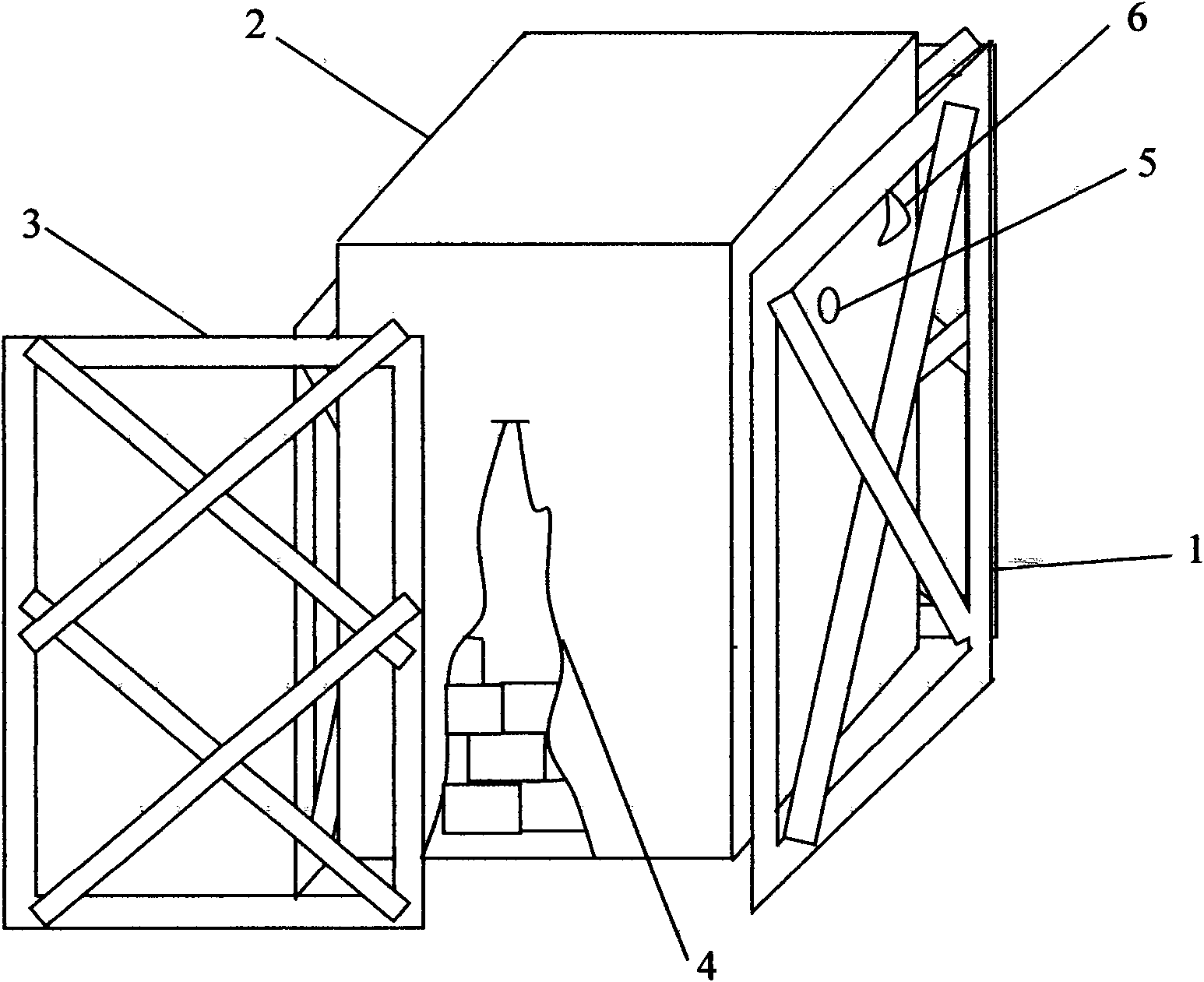
[0052] Such as image 3 The rigid-flexible composite structure formwork shown is composed of two parts: the rigid outer formwork 1 of the outer layer and the flexible inner tire mold 2 arranged in the rigid outer formwork 1 .

[0053] The flexible inner tire mold 2 is a closed bag structure with an openable opening 4, and is provided with a grouting port 5 and a suspension buckle 6. The openable opening length is between 100mm-3000mm.

[0054] The method for carrying out grouting masonry structure construction by using rigid-flexible composite structure formwork is characterized in that it is carried out according to the following steps:

[0055] 1) Fix the flexible inner tube mold 2 on the top plate or on the rigid outer template 1;

[0056] 2) Open the inner tube mold to open the opening 4, put in blocks, bricks, gravel or gangue; close the pocket;

[0057] 3) Fixing the rigid outer formwork 1;

[0058] 4) Connect the grouting pipe to the grouting port 5 and grout;

[0...


PUM


Abstract

The invention relates to a template with a rigid-flexible composite structure, which is composed of two parts: an external rigid template and internal flexible loose tooling arranged in the external rigid template, wherein, the internal flexible loose tooling is an enclosed bag with an expandable opening. The construction method of the template comprises the following steps: fixing the internal flexible loose tooling on a roadway roof or the external rigid template and then connecting pump injection equipment for a concrete conveying pipe for filling concrete into the whole internal loose tooling. If a hard kernel needs to be added to the internal loose tooling, the expandable opening can be opened, building blocks, bricks, detritus or gangue are placed into the opening, and grouting is carried out after sealing. The template with the rigid-flexible composite structure has simple structure, convenient use, and positioning and reshaping features of the rigid template as well as variability of the internal flexible loose tooling so that the whole concrete structural wall can apply a certain setting force to the roof. The method has fast construction speed, high efficiency and good construction effect. The template and the device can be widely applied to industries such as a coal mine, civil engineering, a metallurgical mine, water conservancy, underground construction, national defense and the like.

Description

technical field [0001] The invention belongs to the field of coal mining engineering in coal mines, and in particular relates to a rigid-flexible composite structure formwork and a construction method for a gob-side retaining partition wall. Background technique [0002] Traditional mining face gob entry retention uses wooden piles, dense pillars, gangue bags, material stone walls or concrete continuous walls. The low support strength of wooden stacks and dense pillars cannot meet the needs of most projects. Gangue bags and masonry walls cannot be connected to the roof, resulting in excessive sinking of the roof and poor support effect. The concrete diaphragm wall uses rigid formwork to support the formwork. The disadvantages of these methods are: it requires a lot of manpower and material resources to dry the sand and gravel and mix it with cement. After that, it is bagged and transported to the underground for water mixing again. The labor intensity is high and the constr...

Claims


Application Information

Patent Timeline
Patent Type & Authority Applications(China)
IPC IPC(8): E04G9/10E04G11/06E21F15/04
Inventor 惠兴田
Owner 惠兴田
Why Eureka
Try Eureka