Optical signal processing method, device and system in passive optical network

A signal processing device and passive optical network technology, applied in the field of optical communication, can solve the problems of high cost and high cost, and achieve the effects of reducing optical power loss, large optical power budget, and improving optical power budget and branch ratio.

Active Publication Date: 2011-01-05
山东力晟新型建材科技有限公司
View PDF5 Cites 7 Cited by
  • Summary
  • Abstract
  • Description
  • Claims
  • Application Information

AI Technical Summary

Problems solved by technology

[0003] Traditional PON systems, including GPON and EPON, generally only provide an optical power budget of 28dB (that is, Class B+) for the ODN between EB and ONU, and the coverage distance is less than 20km, and the branch ratio is 1:16 to 1:64 ; But if you want to obtain a 32dB optical power budget, you need to choose a higher-cost Class C+ optical module, which is too expensive

Method used


Image

  • Optical signal processing method, device and system in passive optical network
  • Optical signal processing method, device and system in passive optical network
  • Optical signal processing method, device and system in passive optical network

Examples


Embodiment Construction

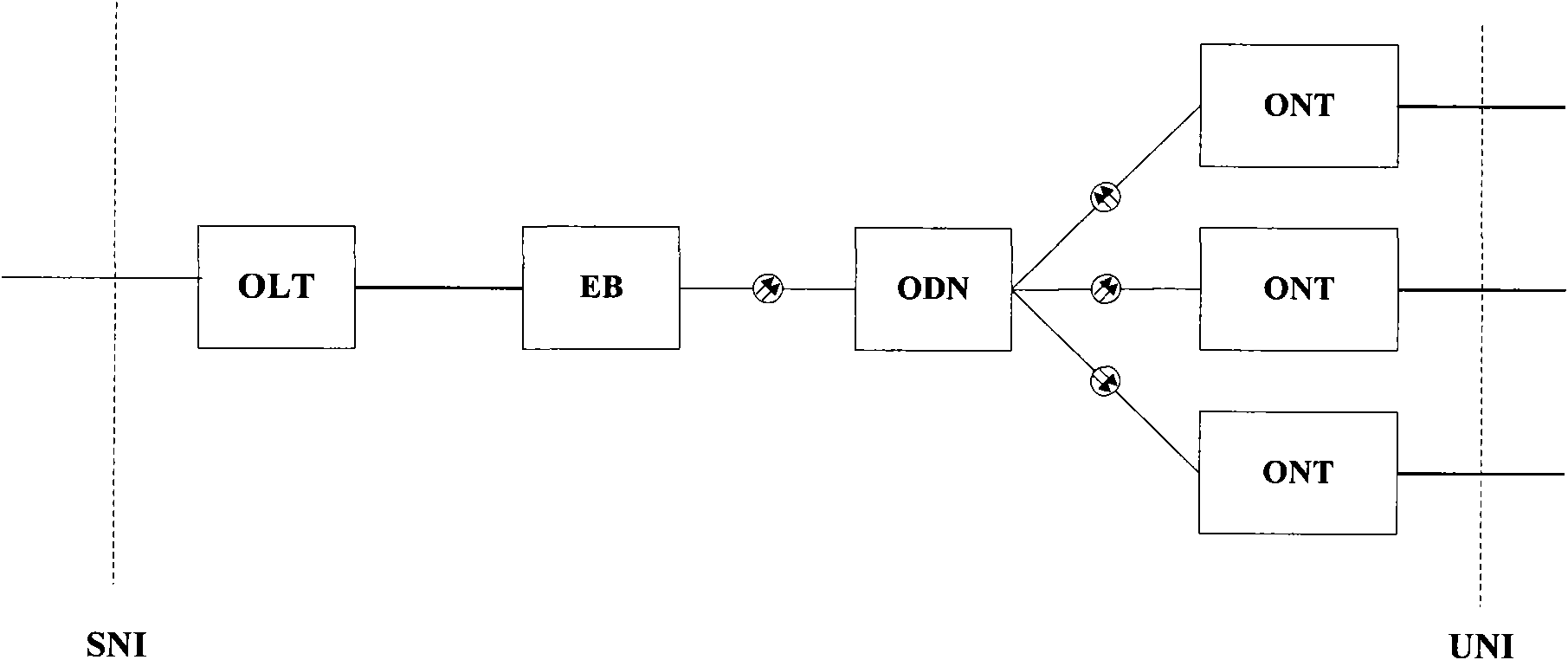
[0021] Embodiments of the present invention propose a mode-coupled EB, which can form a new type of electrical relay PON with a large branch ratio, which can greatly reduce optical power loss and further increase optical power budget.

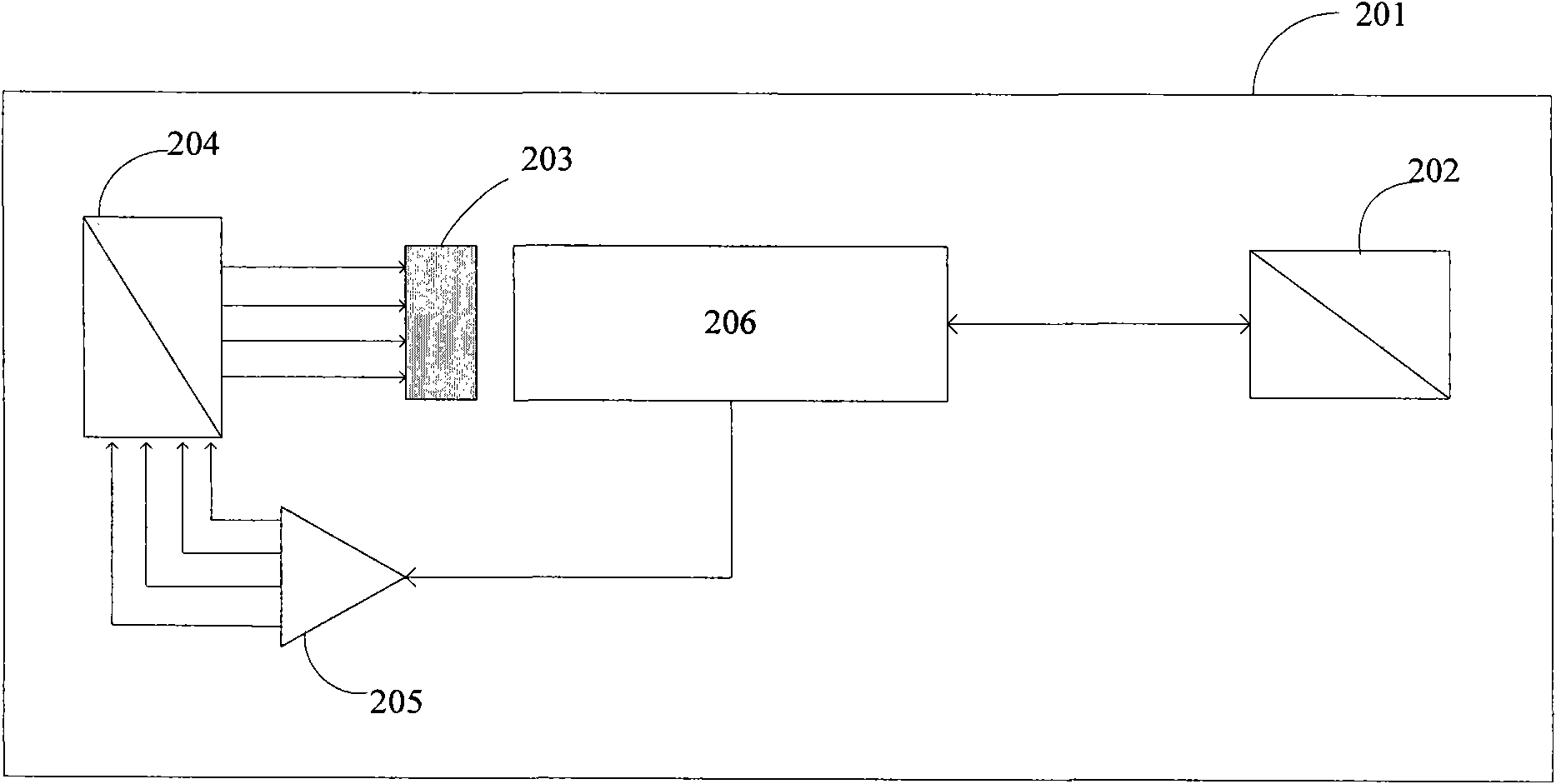
[0022] Embodiment 1 of the present invention provides a mode-coupled EB 201, such as figure 2 The mode-coupling EB201 shown includes a second optical splitter 202, a mode coupling unit 203, a first optical splitter 204, and an optical signal enhancement module 206;

[0023] In the upward direction (from left to right direction)

[0024] The first optical splitter 204 is used to perform multiplex processing on multiple upstream optical signals;

[0025] The mode coupling unit 203 is configured to perform low-loss aggregation of multiple single-mode optical signals or single-channel multi-mode optical signals by matching the modes of the uplink optical signals after the multiplex processing by the optical splitter-204;

[0026] The optical sig...


PUM


Abstract

The embodiment of the invention discloses a signal processing device in a passive optical network, which comprises a first optical splitter 204, a mode coupling unit 203, an optical signal enhancing module 206 and a second optical splitter 202, wherein the first optical splitter 204 is used for combining multiple paths of uplink optical signals; the mode coupling unit 203 is used for performing low loss convergence on multiple paths of single-mode optical signals or single path of multi-mode optical signals by matching the modes of the uplink optical signals combined by the first optical splitter 204 according to the principle of optical field matching and convergence of multiple single-mode optical fibers; the optical signal enhancing module 206 is used for amplifying the optical signals converged by the mode coupling unit 203; and the second optical splitter 202 is used for combining the optical signals amplified by the optical signal enhancing module 206. The embodiment of the invention also discloses a passive optical network and a signal processing method. Therefore, the uplink optical power consumption can be greatly reduced, and a high optical power budget is obtained in a low-cost mode.

Description

technical field [0001] The invention relates to the field of optical communication, in particular to an optical signal processing method, device and system in a passive optical network. Background technique [0002] In the optical access network, PON (passive optical network, passive optical network) technology is a common implementation technology. PON technology is a point-to-multipoint transmission optical access technology. The composition of the PON system can refer to figure 1 Shown: The PON system includes OLT (Optical Line Terminal, Optical Line Terminal), ODN (Optical Distribute Network, Optical Distribution Network), ONU (Optical Network Unit, Optical Network Unit), where the OLT provides the network side interface SNI for the OAN , connect one or more ODNs; the ODN transmits the downlink data of the OLT to each ONU through optical splitting. Although the ODN is a passive optical splitting device, an active EB (Extension Box, extension box) can be added between the...

Claims


Application Information

Patent Timeline
Patent Type & Authority Applications(China)
IPC IPC(8): H04B10/17H04J14/02H04B10/291
Inventor 廖振兴程宁高建河叶飞
Owner 山东力晟新型建材科技有限公司
Why Eureka
Try Eureka