
Buckling-restraining and strengthening system for circular steel tubes

A buckling-constrained, round steel pipe technology, applied in the field of buckling-constrained reinforcement systems, can solve problems such as material waste, safety hazards, and strength decline, and achieve the effects of improving safety reserves, increasing bearing capacity, and simplifying construction operations

Inactive Publication Date: 2011-01-12
TONGJI UNIV
View PDF5 Cites 24 Cited by
  • Summary
  • Abstract
  • Description
  • Claims
  • Application Information

AI Technical Summary

Problems solved by technology

[0010] However, due to the excessive reliance of the section method on welding construction, this has caused a series of inevitable problems: it is difficult to avoid complicated construction operations such as overhead welding when reinforcing the existing structure under load; small angle steel in light steel structures When welded with round steel rods under load, the strength of the heat-affected zone of the weld will drop sharply, which will directly affect the safety of the reinforcement construction; the residual stress generated by the welding operation will also cause safety hazards to the use of the reinforced structure
[0011] In addition, the effect of increasing the section method on the buckling strength of the member is not obvious. When the member is under compression, if buckling is to be avoided, a large amount of reinforcement material is needed to increase the section, which also causes a waste of material.

Method used


Image

  • Buckling-restraining and strengthening system for circular steel tubes
  • Buckling-restraining and strengthening system for circular steel tubes
  • Buckling-restraining and strengthening system for circular steel tubes

Examples


Embodiment 1

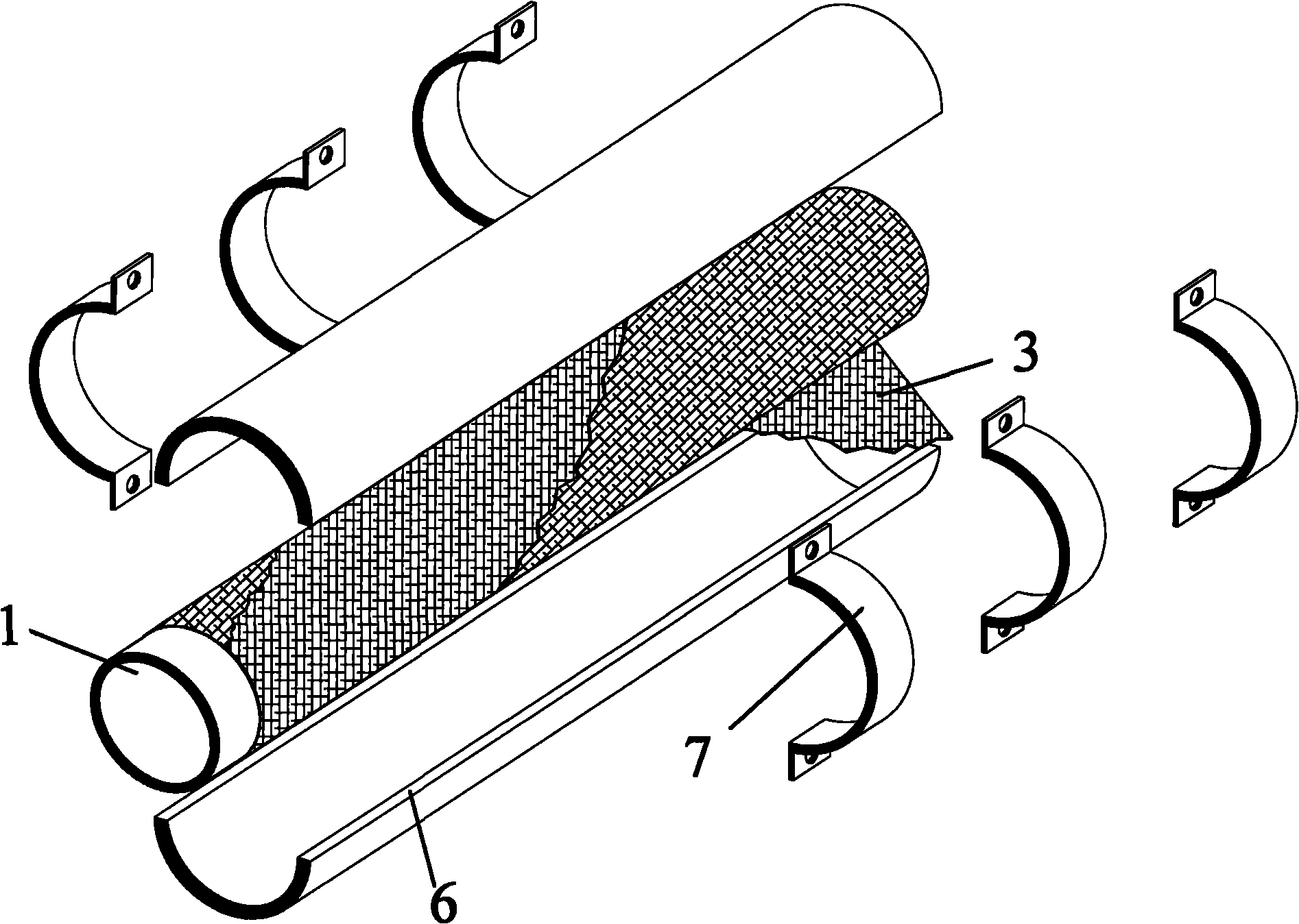
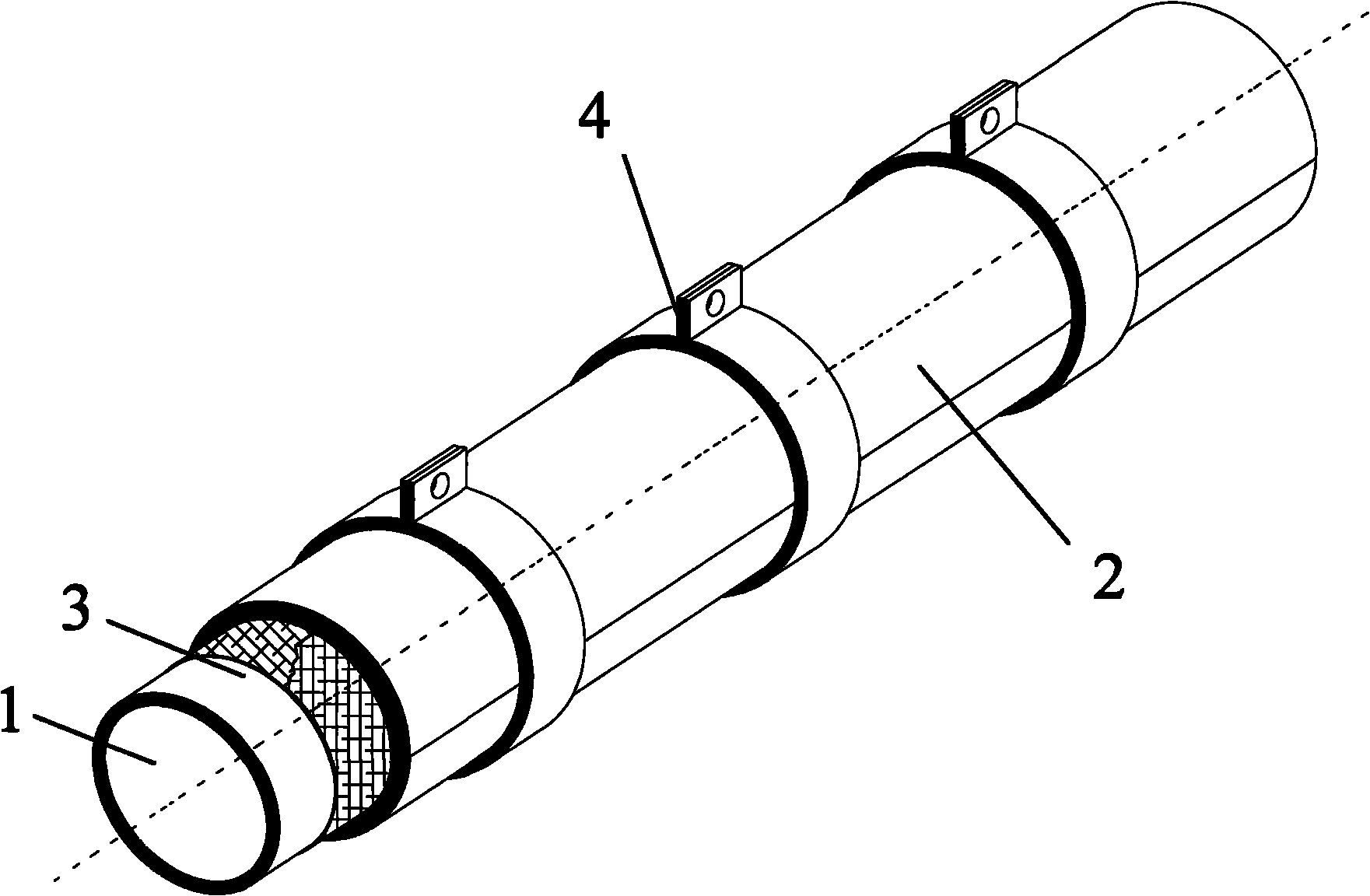
[0029] Embodiment 1: as Figure 1-Figure 4 As shown, the buckling-constrained strengthening system includes the following three parts: axial member unit 1, buckling-constrained unit 2 and debonding unit 3. Axial force component unit 1 is located at the center of the axis, which is the rod to be reinforced in the project, and only bears the axial pressure in the project; the buckling constraint unit 2 is wrapped around the axial force component unit 1, once the axial force component unit 1 buckles under compression deformation, the buckling restraint unit 2 will provide a transverse buckling restraint force to restrain the buckling instability of the axial member unit 1; The debonding effect between the two units is to avoid the axial interaction force between the axial force member unit 1 and the buckling restraint unit 2, so that the buckling restraint unit 2 only produces transverse buckling restraint on the axial force member unit 1 , and the debonding effect is a great fa...


PUM


Abstract

The invention relates to a buckling-restraining and strengthening system for circular steel tubes, which comprises an axial force member unit, a buckling-restraining unit and a debonding unit, wherein the axial force member unit is a member bar of which the engineering structure is to be strengthened, the invention is only applicable to the circular steel tube member bar, the member bar is subjected to buckling collapse in compression in the actual engineering and accordingly has a sharp decrease in the strength, and therefore, the member bar needs to be strengthened; the buckling-restraining unit is an external circular steel tube formed by splicing two semicircular steel tubes and is connected with semicircular steel fasteners arranged at certain intervals by bolts; the debonding unit is arranged between the axial force member to be strengthened and the spliced external circular steel tube and is made of polymeric materials of high debonding performance and certain extrusion resistance. The invention has the advantages of simple structure, convenient construction, obvious strengthening effect and the like, and can be widely used for design construction or reconstruction strengthening of the circular steel tube member bar with a compressed steel structure. By improving and controlling the carrying capacity of the member bar, the technology achieves the purposes of improving the overall carrying capacity of the structure and increasing the emergency capacity of the structure.

Description

technical field [0001] The invention relates to a steel structure reinforcement system, in particular to a buckling restraint reinforcement system for round steel pipes. Background technique [0002] 1. Overview of steel structure reinforcement system [0003] Steel and steel are the most widely used metal building materials in modern structural engineering. In production and construction, after the steel structure has been tested and verified for reliability, if it is deemed not to meet the requirements, it must be reinforced. When the steel structure has the following conditions, it needs to be strengthened: [0004] (a) Due to changes in service conditions, the load increases; [0005] (b) due to shortcomings in the design or construction work, the load-bearing capacity of the structure or its parts does not meet the design requirements; [0006] (c) Due to wear and corrosion, the structure or joints are weakened, and the bearing capacity of the structure or its parts ...

Claims


Application Information

Patent Timeline
IPC IPC(8): E04G23/02
Inventor 谢强高霄
Owner TONGJI UNIV
Learn More