Control method of lockup clutch state collecting circuit

A state acquisition and state control technology, which is applied in the application of locks, building locks, electric number locks, etc., can solve the problems of high power consumption and susceptibility to external electromagnetic interference, achieve low power consumption, enhance practicability, and reduce dependent effect

Active Publication Date: 2011-01-12
UNIV OF ELECTRONICS SCI & TECH OF CHINA
View PDF6 Cites 8 Cited by
  • Summary
  • Abstract
  • Description
  • Claims
  • Application Information

AI Technical Summary

Problems solved by technology

[0006] The purpose of the present invention is to overcome the shortcomings of excessive power consumption and susceptibility to external electromagnetic interference in the existing lock and clutch state acquisition circuit, and provide a lock and clutch state acquisition circuit while proposing a lock and clutch state acquisition circuit control method

Method used


Image

  • Control method of lockup clutch state collecting circuit
  • Control method of lockup clutch state collecting circuit
  • Control method of lockup clutch state collecting circuit

Examples


Embodiment 1

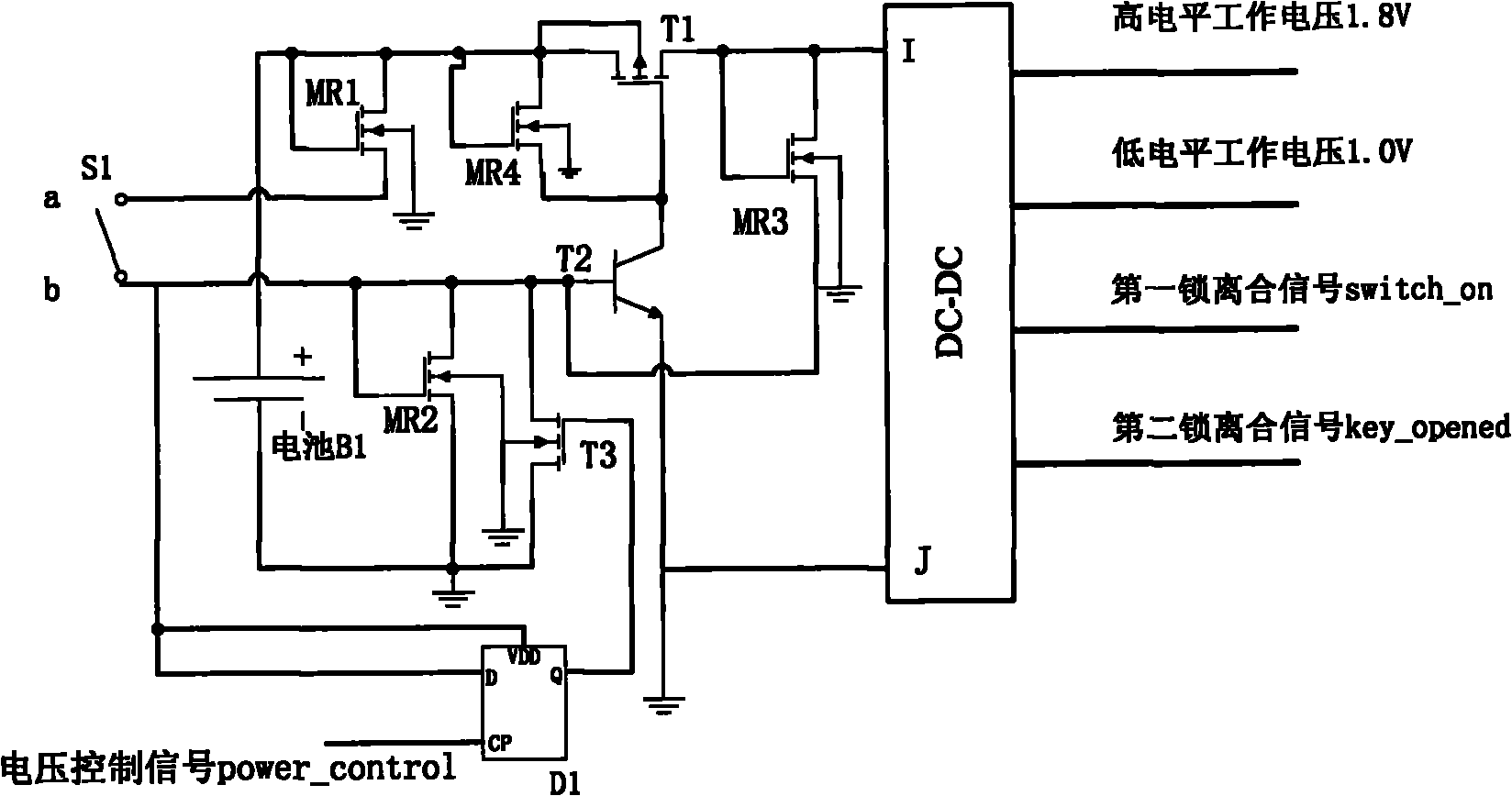
[0033] Example 1: Such as figure 1 As shown, the circuit structure of the lock and clutch state acquisition circuit is as follows: the switch state acquisition circuit includes a switch S1, a first NMOS tube MR1, a second NMOS tube MR2, a third NMOS tube MR3, a fourth NMOS tube MR4, a PMOS tube T1, and a triode. T2, the fifth NMOS tube T3, the power battery B1, the trigger D1 and the DC-DC voltage conversion circuit.

[0034] Combine figure 1 The connection mode of each device and port is as follows: The power supply battery B1 is connected to the overall circuit from the outside; after the gate and drain of the first NMOS transistor MR1 are connected, it is connected to the positive electrode of the battery B1; The source of the NMOS transistor MR1 is connected to the first terminal a of the switch S1; the gate and drain of the second NMOS transistor MR2 are connected to the second terminal b of the switch S1; the second NMOS transistor MR2 The source is connected to the ground;...

Embodiment 2

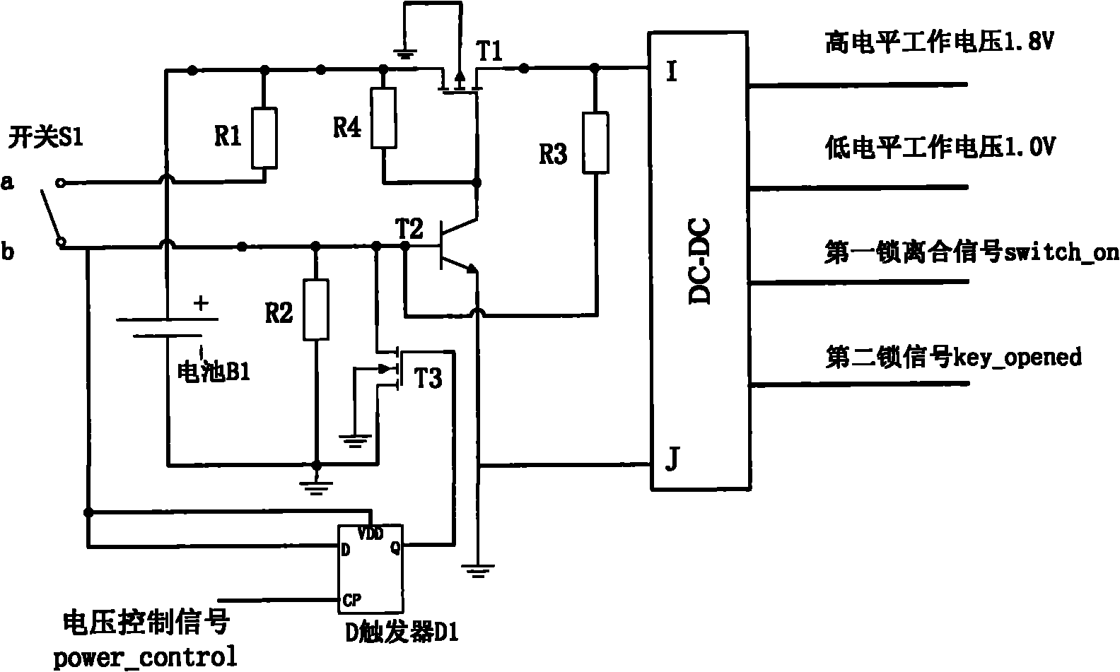
[0041] Example 2: Such as image 3 As shown, a lock-clutch state acquisition circuit includes a lock-clutch signal switch (S1), a first resistor R1, a second resistor R2, a third resistor R2, a fourth resistor R4, a PMOS transistor T1, a triode T2, and a fifth NMOS The tube T3, the power supply battery B1, the trigger D1 and the direct current-direct current (DC-DC) voltage conversion chip, the first resistor R1 is connected to the first end a of the lock clutch signal switch S1, and the second resistor R2 is connected to the lock clutch The second terminal b of the signal switch S1 is connected; the base of the transistor T2 and the drain of the PMOS transistor T1 are connected through a third resistor R3; the source and gate of the PMOS transistor T1 are connected through a fourth resistor R4; The source of the PMOS transistor T1 is connected to the positive electrode of the power battery B1; the source of the PMOS transistor T1 is connected to the first end a of the lock and ...


PUM


Abstract

The invention relates to a control method of a lockup clutch state collecting circuit. When the radio frequency identification (RFID) electronic tag of the collecting circuit integrating the lockup clutch state or the RFID device of the collecting circuit adopting the lockup clutch state is in a RFID field, the control method comprises the step (a) and other steps, wherein the step (a) is that the RFID electronic tag or the RFID device enters the RFID field, the radio frequency analog front-end of the RFID electronic tag is electrified to work. The beneficial effects of the invention are as follows: the lockup clutch state collecting circuit of the invention has the advantages of low power consumption and interference resistance; and as the lockup clutch state collecting circuit can be integrated in the electronic tag, the collecting circuit is easier to combine with the electronic tag to be used as the monitoring node of the Internet of things for moving containers and proof boxes in the logistics industry, thus timely monitoring the lockup clutch state of containers and proof boxes and ensuring the safety of moving containers and proof boxes.

Description

Technical field [0001] The invention belongs to the technical field of electronic circuits, and in particular relates to a control method combined with a lock clutch state acquisition circuit of a lock and a radio frequency identification technology. Background technique [0002] Radio Frequency Identification (RFID) technology uses radio frequency to communicate over long distances to achieve the purpose of identification, tracking, positioning, and management of items. Radio frequency identification technology has broad application prospects in many fields such as industrial automation, commercial automation, transportation control management, anti-counterfeiting, and even military applications, and has attracted widespread attention. [0003] Electronic tags and readers made using radio frequency identification technology are widely used, especially as the electronic tags of the nodes of the Internet of Things, which can effectively store various information of attached items an...

Claims


Application Information

Patent Timeline
Patent Type & Authority Applications(China)
IPC IPC(8): E05B49/00G06K19/07
Inventor 文光俊咸凛王耀
Owner UNIV OF ELECTRONICS SCI & TECH OF CHINA
Why Eureka
Try Eureka