Component structure of light-emitting diode light source with heat radiation base

A technology for light emitting diodes and light source assemblies, which is applied in the field of light emitting diode light source assembly structures, can solve problems such as inconvenience, damage to the light emitting diode elements of circuit substrates, and difficulty in clamping the circuit substrates, and achieves the effect of saving processing.

Inactive Publication Date: 2011-01-12
POWER LIGHT TECH
View PDF1 Cites 14 Cited by
  • Summary
  • Abstract
  • Description
  • Claims
  • Application Information

AI Technical Summary

Problems solved by technology

[0004] Although the above-mentioned previous proposals can combine the circuit board and the metal support without using screws or adhesives, since the circuit board and the metal support are both made of rigid materials, it is not easy to attach the flange or the elastic clip of the circuit board Snap into the hole of the metal support, if the flange or the elastic piece is forced to snap into the hole of the metal support by external force, it is easy to cause damage to the circuit board or the LED element
[0005] It can be seen that the above-mentioned existing light-emitting diode light source assembly structure obviously still has inconvenience and defects in structure and use, and needs to be further improved urgently.
In order to solve the above-mentioned problems, the relevant manufacturers have tried their best to find a solution, but for a long time no suitable design has been developed, and the general product has no suitable structure to solve the above-mentioned problems. This is obviously the relevant industry. Urgent problem

Method used


Image

  • Component structure of light-emitting diode light source with heat radiation base
  • Component structure of light-emitting diode light source with heat radiation base
  • Component structure of light-emitting diode light source with heat radiation base

Examples


Embodiment Construction

[0048] In order to further illustrate the technical means and effects adopted by the present invention to achieve the predetermined purpose of the invention, the following describes the specific implementation of the structure of the light-emitting diode light source assembly with a heat dissipation base according to the present invention with reference to the accompanying drawings and preferred embodiments. Structure, features and their efficacy are described in detail.

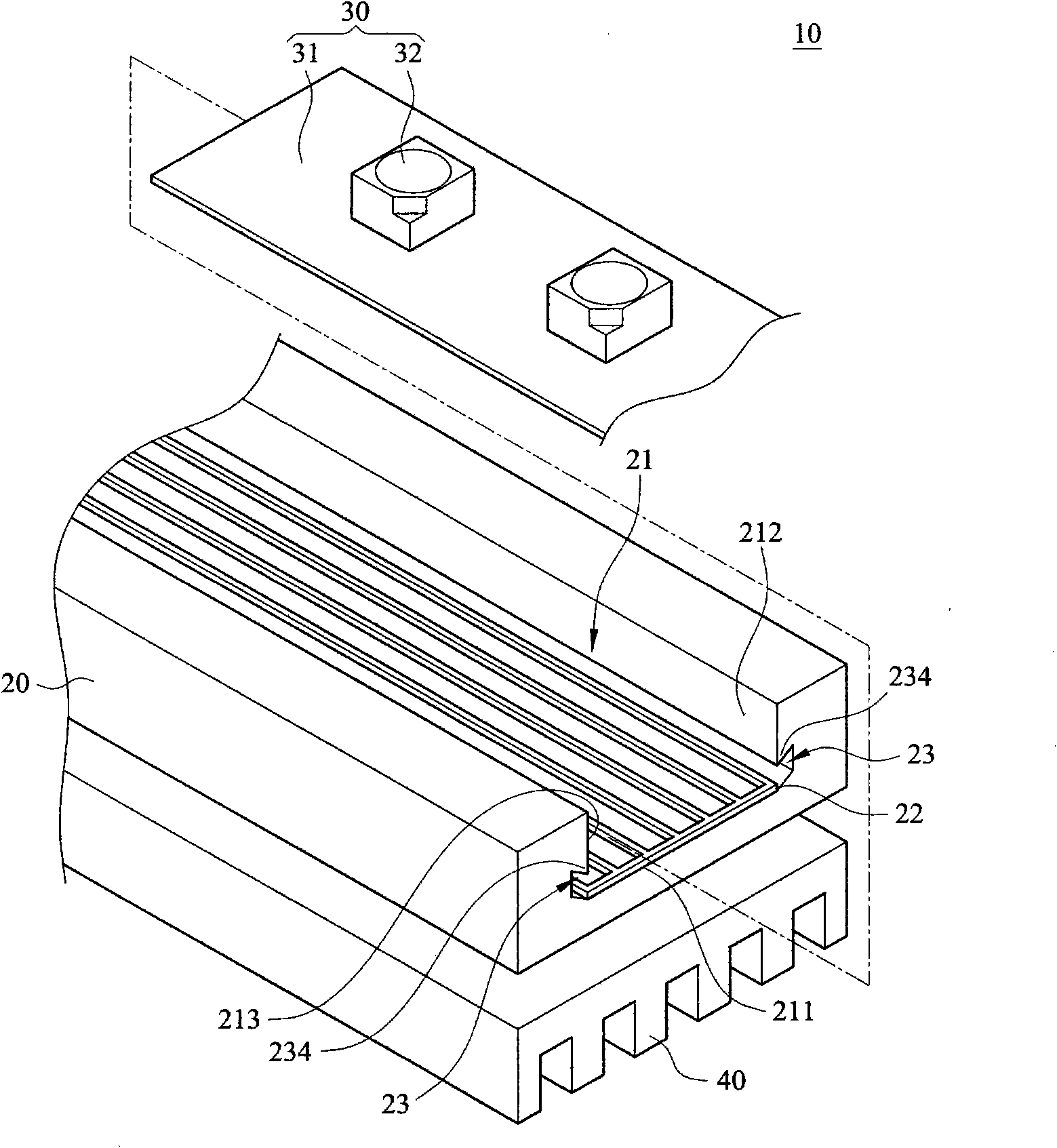
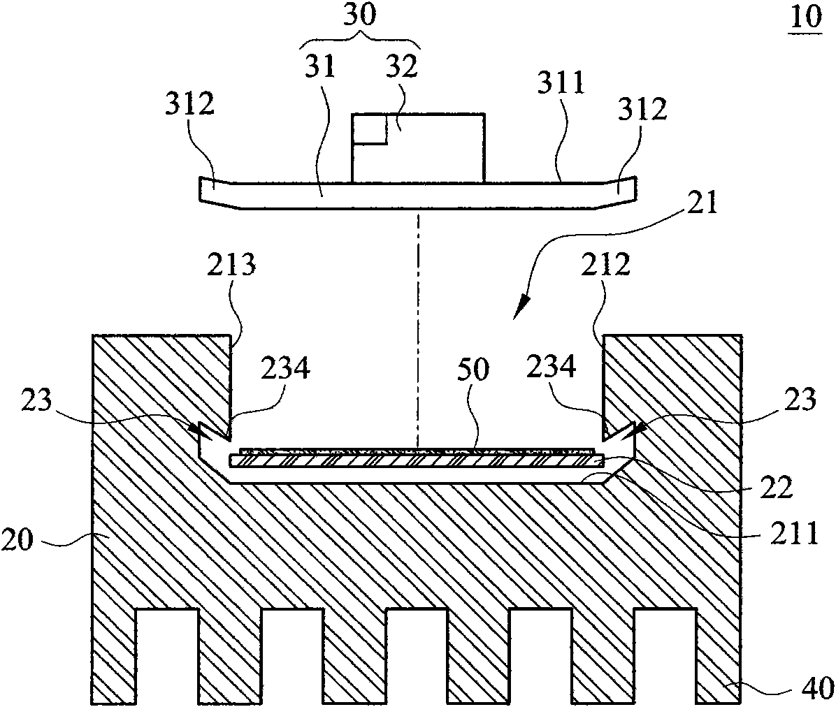
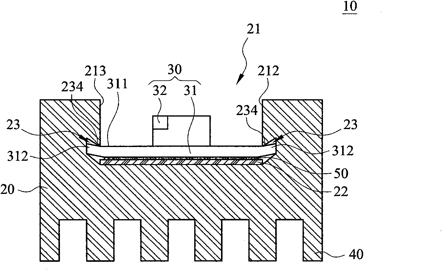
[0049] figure 1 It is an exploded perspective view of a light-emitting diode light source assembly structure 10 with a heat dissipation base according to the present invention. figure 2 It is a cross-sectional exploded embodiment diagram of an LED light source assembly structure 10 with a heat dissipation base according to the present invention. image 3 It is a cross-sectional embodiment diagram of an LED light source assembly structure 10 with a heat dissipation base according to the present invention. ...


PUM


Abstract

The invention relates to a component structure of a light-emitting diode light source with a heat radiation base, comprising a heat radiation base and a light strip, wherein the light strip is provided with a flexible circuit board and a light-emitting diode element, and the light-emitting diode element is arranged on the flexible circuit board and is electrically connected with the flexible circuit board. Due to that the heat radiation base is provided with a fixing groove, the heat radiation base and the two ends of the flexible circuit board can be clamped mutually, thereby achieving the heat conductive combination of the flexible circuit board on the heat radiation base. By the flexibility of the flexible circuit board, the flexible circuit board can be clamped on the heat radiation base easily through the fixing groove, thereby realizing the function of saving the processing and material costs of the light strip to be installed.

Description

technical field [0001] The invention relates to an LED light source assembly structure with a heat dissipation base, in particular to an LED light source assembly structure with a heat dissipation base using a flexible circuit board. Background technique [0002] Generally, light-emitting diode light source components are mostly soldered on the FR4 substrate or aluminum substrate by surface mount technology (SMT), and then a heat dissipation mechanism is set on the back of the FR4 substrate or aluminum substrate to make the light-emitting diodes The heat of the components can be dissipated by the heat dissipation mechanism. However, the heat dissipation mechanism must be fixed with screws or adhesives to fix the heat dissipation mechanism and the FR4 substrate or aluminum substrate. However, if the FR4 substrate or aluminum substrate is locked with screws, the cost of drilling, tapping, and screw components will increase. The light-emitting diode element itself is also a h...

Claims


Application Information

Patent Timeline
Patent Type & Authority Applications(China)
IPC IPC(8): F21S2/00F21V29/00F21V23/00F21V17/10F21V7/22F21Y101/02F21V29/70F21V29/74F21V29/89
Inventor 张忠民黄永吉
Owner POWER LIGHT TECH
Why Eureka
Try Eureka