LED heat radiation module

A technology of heat dissipation module and LED light source, applied in lighting and heating equipment, cooling/heating device of lighting device, lighting device, etc., can solve the problems of unstable performance, short service life, poor heat dissipation effect, etc. The effect of improving heat dissipation efficiency and reducing cost

Inactive Publication Date: 2011-01-12
周焕球
View PDF3 Cites 8 Cited by
  • Summary
  • Abstract
  • Description
  • Claims
  • Application Information

AI Technical Summary

Problems solved by technology

[0005] The technical problem to be solved by the present invention is to provide an LED heat dissipation module to s

Method used


Image

  • LED heat radiation module
  • LED heat radiation module
  • LED heat radiation module

Examples


Example Embodiment

[0026] Embodiment one:

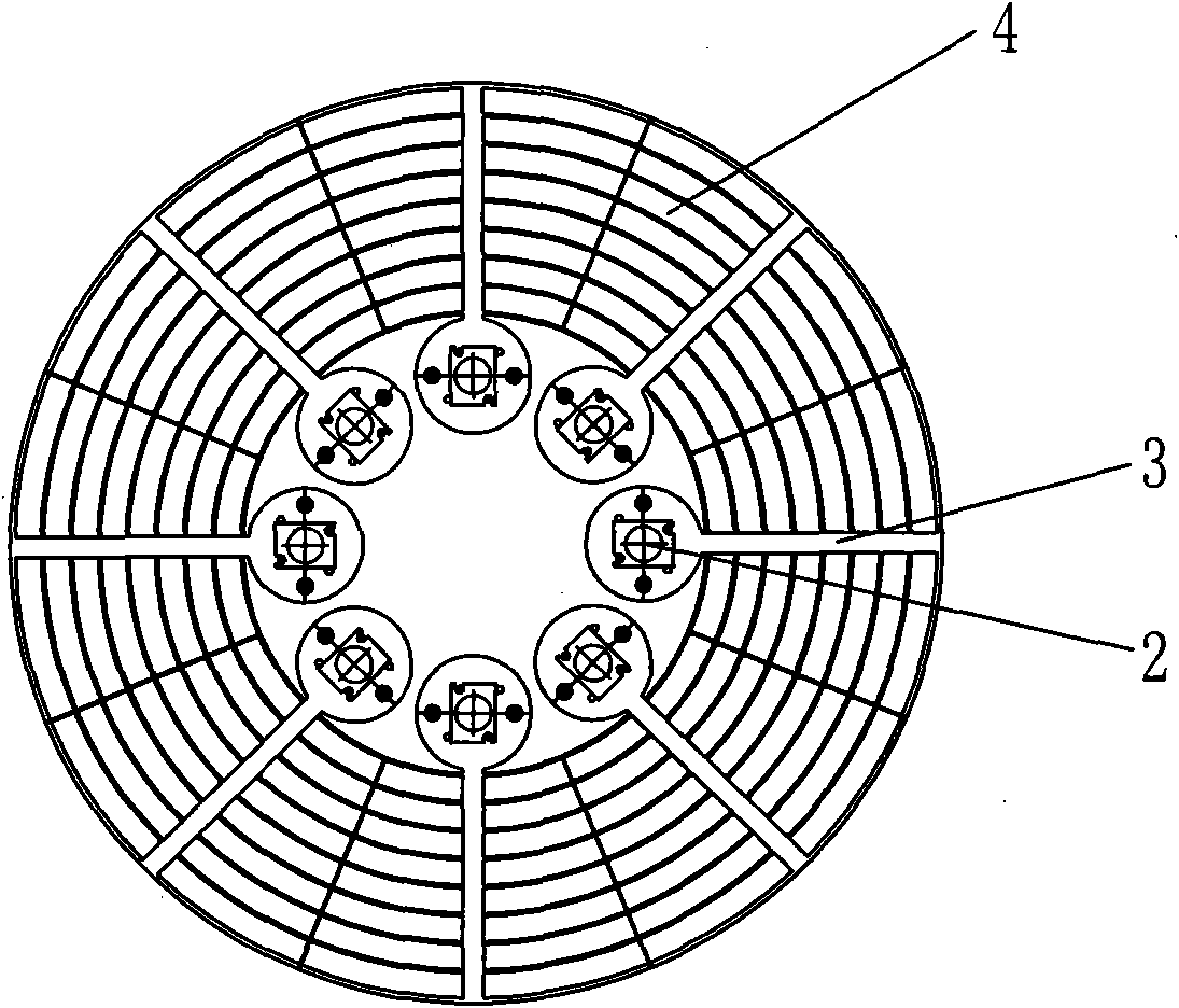
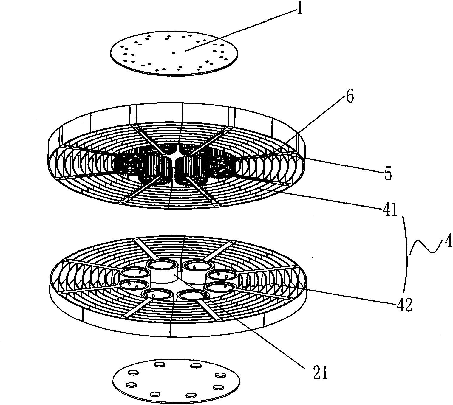
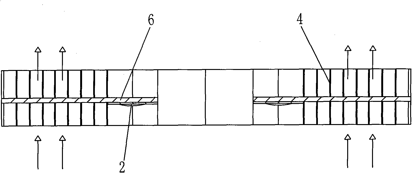
[0027] as attached Figure 1~3 As shown, what this embodiment discloses is an LED heat dissipation module with light weight and good heat dissipation effect. The heat dissipation module includes an LED light source module 2 driven by an LED driver and a heat sink connected to the LED light source module 2. The LED light source module 2 is installed in the center of the heat sink. Formed by fins 4, the LED light source module 2 is connected and installed on the ribs 3 of the heat sink. The heat emitted by the LED light source module 2 is conducted to the annular fins 4 through the ribs 3, and the air flows through the annular fins from bottom to top and natural convection. The heat on sheet 4 dissipates to the outside.

[0028] The annular fins 4 of the above-mentioned radiator include an upper annular fin 41 and a lower annular fin 42, and the upper and lower annular fins 41, 42 are fixedly connected to each other by a fixing member. On the upper and...

Example Embodiment

[0033] Embodiment two:

[0034] as attached Figure 9-10 As shown, the structure of the LED cooling module disclosed in this embodiment is similar to that in Embodiment 1, the difference is that one end of the heat pipe 6 is connected to a vapor chamber 7, the other end is installed in the heat conduction groove 5, and the LED light source module 2 is installed On the lower surface of the vapor chamber 7 , the LED driver is installed on the vapor chamber 7 and covered with the fixing plate 1 .

[0035] In this embodiment, when the heat generated by the operation of the LED light source module 2 is transferred to the soaking plate 7, the heat is conducted from the soaking plate 7 to the heat pipe 6, and the heat transfer liquid inside the heat pipe 6 absorbs heat and is evaporated, then condenses and releases heat in the heat conduction The inner surface of the condensing part of the tube 6 conducts the heat to the outer surface of the heat transfer tube 6, and the condensed l...


PUM


Abstract

The invention discloses an LED heat radiation module, comprising of an LED light source module driven by an LED driver, and a heat radiation body connected with the LED light source module. The LED light source module is arranged in the center of the heat radiation body, and the heat radiation body consists of annular fins connected by a plurality of ribs. The LED light source module is connected on the ribs of the heat radiation body, the heat of the LED light source module is conducted to the annular fins through the ribs, and the heat of the annular fins is dissipated to the outside by the natural convection of air from bottom to top. Gaps are arranged between the annular fins of the heat radiation module, and the heat of the LED light source module can also be conducted to the annular fins on each layer through heat conduction grooves and heat conduction tubes, therefore the structure can greatly enhance the heat radiation effect of LED pendent lamp with the LED heat radiation module, meanwhile the structure of the heat radiation module has reduced weight and less production cost compared with the similar fin heat radiation structure, dust are rarely accumulated on the heat radiation fins arranged vertical the ground, and the heat radiation effect is enduring and efficient.

Description

technical field [0001] The invention relates to a heat dissipation module, in particular to a heat dissipation module applied to the heat dissipation of high-power light-emitting diode pendant lamps and lamps. Background technique [0002] LED (Light Emitting Diode, light-emitting diode) has the advantages of small size, impact resistance, long life, low power consumption, cold light emission and no mercury pollution. It is widely used in enterprises, institutions, halls, conference rooms, workshops, shops, stations , hospitals, hotels, guesthouses, parks, leisure squares and street communities and other indoor and outdoor places. [0003] At present, only 15-20% of the input power of high-power LEDs is converted into light, and the remaining 80-85% is converted into heat and released. If the heat is not discharged in time, the junction temperature of the LED grain will be too high. High and affect the luminous efficiency and service life and other issues. [0004] Existin...

Claims


Application Information

Patent Timeline
IPC IPC(8): F21V19/00F21V29/00F21V17/00F21Y101/02F21V29/71F21V29/77
Inventor 周焕球
Owner 周焕球
Why Eureka
Try Eureka