
Combustion chamber structure for heat exchanger

A technology for heat exchangers and combustion chambers, applied in the field of combustion chambers, can solve problems such as failure to achieve high-efficiency goals, affecting thermal efficiency, and insufficient combustion, reducing the generation of harmful gases such as carbon monoxide, increasing the heat-absorbing area, and the spread of combustion flames. short distance effect

Active Publication Date: 2011-01-12
WUXI XIZHOU MACHINERY
View PDF9 Cites 1 Cited by
  • Summary
  • Abstract
  • Description
  • Claims
  • Application Information

AI Technical Summary

Problems solved by technology

At present, the heat exchange efficiency of domestic heat exchangers is generally between 70% and 85%, and most of the combustion chambers are cylindrical, semi-spherical, etc., which cannot achieve the goal of high efficiency at all; Affects thermal efficiency, complete combustion, high thermal efficiency, insufficient combustion, causing energy waste and endangering health

Method used


Image

  • Combustion chamber structure for heat exchanger
  • Combustion chamber structure for heat exchanger
  • Combustion chamber structure for heat exchanger

Examples


Embodiment Construction

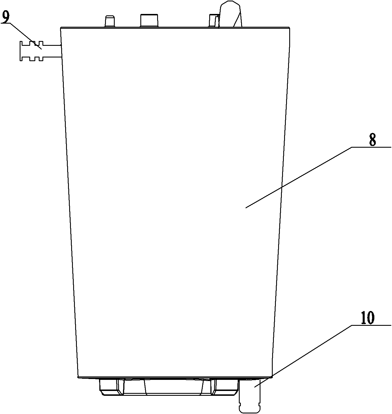
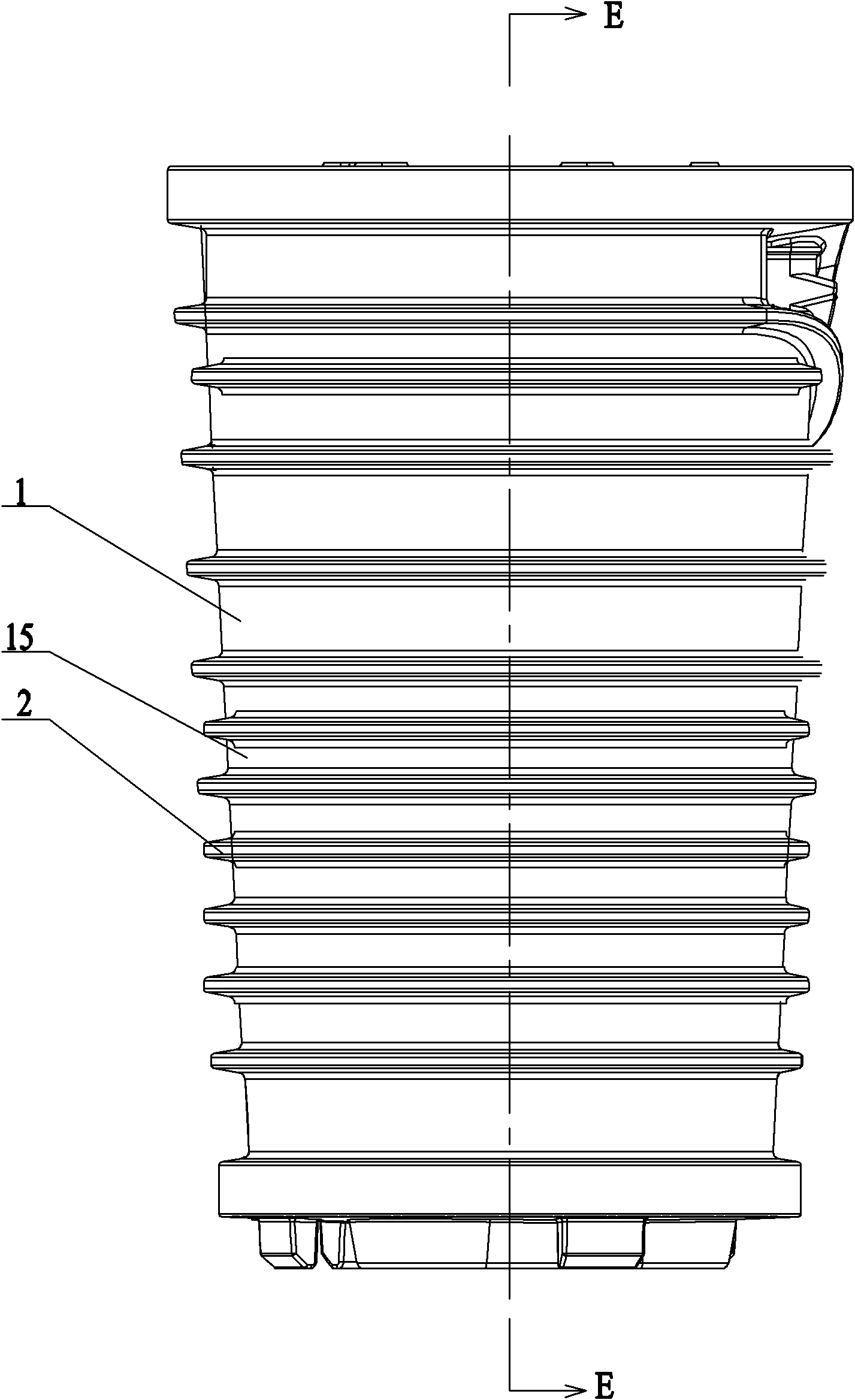
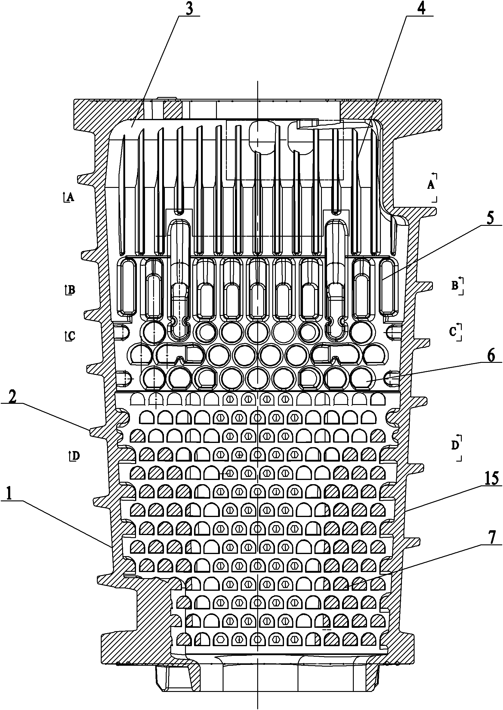
[0016] Such as Figure 1~Figure 7 As shown: the present invention includes a combustion chamber 1, a positioning boss 2, a combustion chamber cavity 3, a thin and long fin 4, a thick and short fin 5, a first heat exchange fin 6, a second heat exchange fin 7, a casing 8, and a water inlet pipe 9. Outlet pipe 10 , first airflow channel 11 , second airflow channel 12 , third airflow channel 13 , end cover 14 and heat transfer medium channel 15 .

[0017] Such as figure 1 and figure 2 As shown: the heat exchanger includes an outer shell 8 and a combustion chamber 1 located in the outer shell 8, the outer wall of the combustion chamber 1 is provided with a positioning boss 2 that closely fits the combustion chamber 1, so There are a plurality of positioning bosses 2, which are evenly distributed along the outer peripheral surface of the combustion chamber 1; heat transfer medium channels 15 are formed between adjacent positioning bosses 2; and a combustion chamber cavity 3 is fo...


PUM


Abstract

The invention relates to a combustion chamber structure for a heat exchanger. The combustion chamber structure comprises a combustion chamber, a combustion chamber cavity is formed in the combustion chamber, and a heat transfer medium passage is formed between positioning lug bosses on the outer wall of the combustion chamber; heat exchange fins are arranged in the combustion chamber; and the heat exchange fins are distributed from thin to thick between the top and the bottom of the combustion chamber. When the capacity of the combustion chamber is unchangeable, the combustion chamber structure increases the heat absorption area, shortens the propagation distance of the combustion flame, reduces the deflagration probability, reduces heat loss and improves the heat conversion efficiency; when the gas enters the combustion chamber cavity from the top of the combustion chamber, high cyclone movement is generated; when the gas just enters the combustion chamber, the speed of the gas is maximum speed; because of airflow movement, the flame propagation in a rapid combustion period is accelerated, the cooling of the mixed gas at the tail end is increased, combustion change between cycles is reduced, and the ignition boundary of the mixed gas is enlarged; the combustion chamber structure is favorable for combusting thinner mixed gas so that the combustion is more full, the generation of harmful gas such as carbon monoxide is reduced, and the fuel gas loss is reduced; and the combustion chamber structure is safe and reliable.

Description

technical field [0001] The invention relates to a combustion chamber, in particular to a combustion chamber structure for a heat exchanger, belonging to the technical field of heat exchangers. Background technique [0002] The role of the combustion chamber for heat exchangers is to convert the chemical energy of the combustion gas into heat energy with practical value, but the structural design of the combustion chamber directly affects the heat transfer efficiency of the heat exchanger, the combustion performance of the heat exchanger and safety. With the development of heat exchangers in the direction of high efficiency, energy saving, consumption reduction and environmental protection, the design of the combustion chamber is becoming more and more important. At present, the heat exchange efficiency of domestic heat exchangers is generally between 70% and 85%, and most of the combustion chambers are cylindrical, semi-spherical, etc., which cannot achieve the goal of high...

Claims


Application Information

Patent Timeline
IPC IPC(8): F24H9/18F23D14/00
Inventor 包建忠
Owner WUXI XIZHOU MACHINERY
Learn More