
Xenon short arc lamp for digital a projector

A technology for projectors and short-arc lamps, applied to gas discharge lamps, parts of gas discharge lamps, discharge lamps, etc., can solve problems such as the end of life, and achieve the effect of long service life

Active Publication Date: 2011-01-12
USHIO DENKI KK
View PDF5 Cites 1 Cited by
  • Summary
  • Abstract
  • Description
  • Claims
  • Application Information

AI Technical Summary

Problems solved by technology

[0032] In addition, even though conventionally known technologies have improved the flicker life of the xenon lamp by utilizing, for example, the formation of the carbonized layer and the shape of the tip of the cathode, the life of the xenon lamp ends in a very short time of 200 to 350 hours after the lamp is turned on.

Method used


Image

  • Xenon short arc lamp for digital a projector
  • Xenon short arc lamp for digital a projector
  • Xenon short arc lamp for digital a projector

Examples


example 2

[0148] Lamp 2 (reference example 2) is a xenon short-arc lamp for digital projectors for DLP, and the sealing pressure, the current density at the tip of the cathode, and the load on the tube wall are set high in order to be a high-intensity lamp. The specific specifications are as above.

[0149] In the molding process of the arc tube, when the arc tube is expanded, the same dry gas (N2) as that of the above-mentioned lamp 1 is used, and the concentration of the OH group in the inner surface of the arc tube is maintained at the level of the raw material before molding, and is as low as 5 wt-ppm . Also, as in lamp 1, a carbide layer was formed on the surface of the tapered portion of the cathode body by a conventionally known method, and a tantalum getter was arranged inside the arc tube.

[0150] The lamp 2 thus turned on has a flicker life of 260 hours, which is an extremely short life compared with the lamp 1 .

[0151] In addition, analyzing lamp 2, the total carbon cont...

Embodiment 1

[0162] Then, the lamp 4 (Example 1) in which the amount of carbon in the arc tube was increased was fabricated.

[0163] In addition, in the lamp 4 (Example 1), it is the same as the lamp 3 (Reference example 3) in that a light-emitting tube having an increased OH group concentration in the inner surface layer is used as a long-term water supply source.

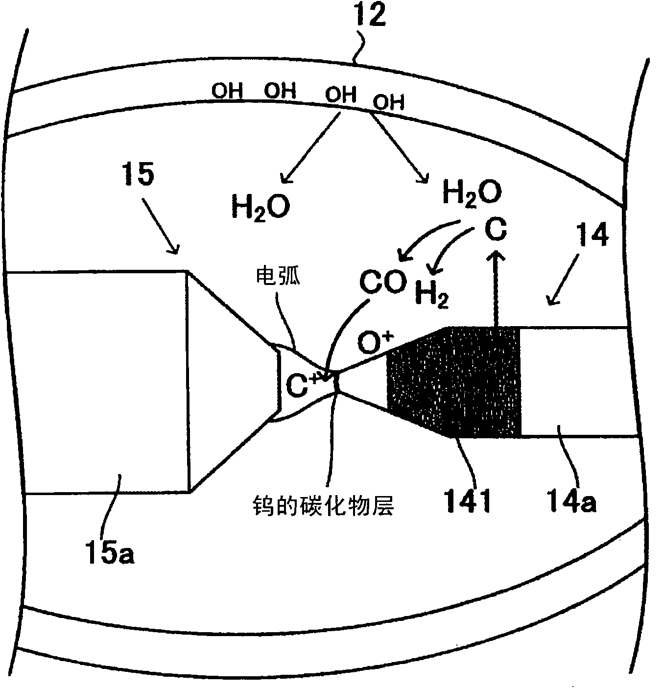
[0164] Here, various studies were conducted as a method for increasing the amount of carbon, but in this example, the amount of carbon was increased by increasing the area of ​​the surface of the cathode to be carbonized. For example, in the carbonized layer forming step, the amount of carbon existing inside the arc tube, that is, the front end of the cathode can be adjusted according to the amount of the coating agent containing carbon, the area of ​​the region where the carbonized layer is formed, the temperature of the high-temperature carburizing treatment, and the like. The amount of carbon configured on the carbide layer ...

Embodiment 2

[0168] A lamp 5 (Example 2) having the same structure as the above lamp 4 (Example 1) except that the amount of carburization of the cathode was further increased was fabricated. When the lamp 5 is turned on, the flickering lifespan is 540 hours, which can further prolong the lifespan. Analyze the amount of carbon in the lamp 5, relative to 1 cm of the inner volume of the luminous tube 3 is 3.0 μmol.


PUM


Abstract

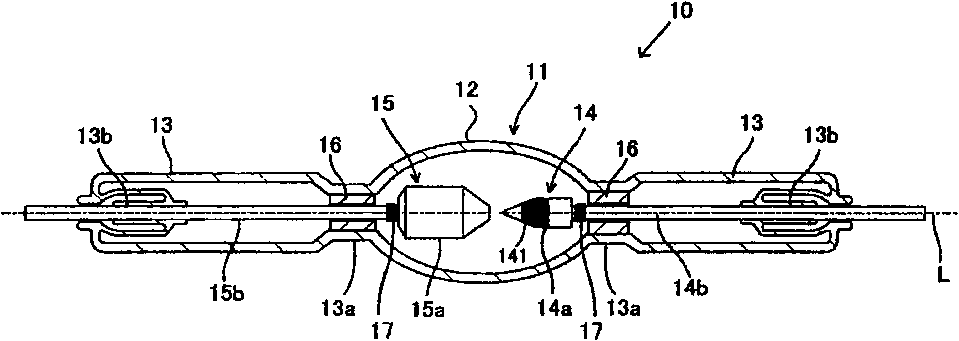
The invention provides a xenon short arc lamp for a digital projector with long service life which prevents concave and convex existed at a front end surface of a cathode for a long time after lightening the lamp, and restrains the flicker phenomenon for a long time. The xenon short arc lamp for the digital projector includes an anode, the cathode having a cathode main body that is made of tungsten containing electron emissive material, and an arc tube made of silica glass. The xenon short arc lamp for the digital projector is characterized in that a supply source of carbon is formed on a metal portion in the arc tube except a tip area of the cathode, and the carbon is supplied to the tip of the cathode through a gaseous phase during lamp lighting, so that a surface layer of the cathode is melt; or the cathode is on a surface layer of the front end surface and has a belt phase of carbide having tungsten in a tungsten phase.

Description

technical field [0001] The present invention relates to a xenon short-arc lamp for a digital projector used as a light source in, for example, a digital projector using DLP (Digital Light Source Processor; registered trademark) technology using a DMD (Digital Micromirror Device; registered trademark). Background technique [0002] Traditionally, standard film projectors used in cinema projection systems shone 35mm film through an aperture to project onto a screen. Figure 9 It is a figure explaining the structure of the projector for film. On the film 71, video frames (hereinafter simply referred to as frames) representing continuous content are recorded at regular intervals. The film 71 is conveyed by a moving mechanism not shown, and passes through the picture gate 72 from top to bottom. The light gathered from the light source unit 73 passes through the hole formed in the picture gate 72 and illuminates the picture recorded on the film 71 . [0003] The size of one fram...

Claims


Application Information

Patent Timeline
IPC IPC(8): H01J61/073H01J61/26H01J61/12G03B21/00G03B21/14H01J61/16H01J61/30H01J61/86
CPCH01J61/0735H01J61/86
Inventor 森本俊一北川铁也内野亚纪子有本智良
Owner USHIO DENKI KK
Learn More