Forging mold for cantilever type hardware fitting base of electrified railway contact network parts

A technology of electrified railway and catenary, which is applied in the field of forging molds, can solve the problems of high scrap, quality not up to the requirement, and small contact area of ​​ears, etc., and achieve the effect of increasing contact area, reducing manufacturing cost, and good force effect

Inactive Publication Date: 2011-01-19
RUGAO DASHENG LINE EQUIP
View PDF8 Cites 5 Cited by
  • Summary
  • Abstract
  • Description
  • Claims
  • Application Information

AI Technical Summary

Problems solved by technology

At present, there are two ways to produce this kind of metal base: one is casting method, which has the disadvantages of loose internal structure, shrinkage cavity, cracks and other defects, the quality cannot meet the requirements, and there are great safety hazards. And scrap more
[0004] In addition, the current metal base mold is limited by the structure. The taper of the inner surface of the ear of the forged metal base must be more than 3°, otherwise the mold cannot be pulled out, which will cause another connection between the two ears when the subsequent product is assembled and used. The contact area between the piece and the ear of the hardware base is small, and the force effect is poor

Method used


Image

  • Forging mold for cantilever type hardware fitting base of electrified railway contact network parts
  • Forging mold for cantilever type hardware fitting base of electrified railway contact network parts
  • Forging mold for cantilever type hardware fitting base of electrified railway contact network parts

Examples


Embodiment Construction

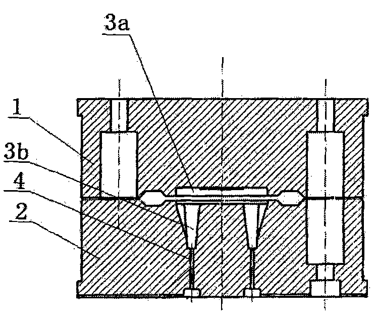
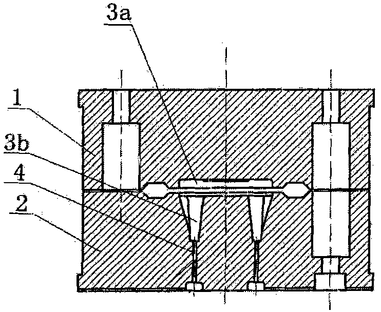
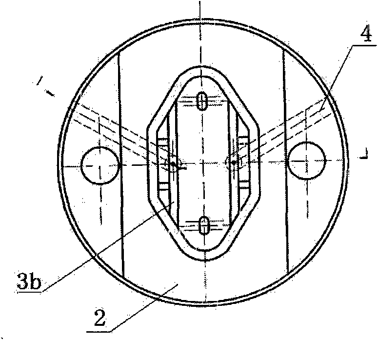
[0012] like figure 1 , 2 As shown, it includes an upper mold 1 and a lower mold 2. The cavities of the upper mold 1 and the lower mold 2 are combined to form the cavity 3 of the metal fitting base. The cavity 3 is composed of the base 3a and the ears 3b symmetrically arranged on both sides. The taper in the middle of the inner surface of the cavity ear 3b is 1-2°.

[0013] The inner wall of the cavity 3 is provided with an exhaust channel 4 that communicates with the outside world. The exhaust channel 4 is located at the bottom of the cavity 3, one end communicates with the cavity 3, and the other end goes vertically down to the lower end surface of the lower die 2. It extends to the side and communicates with the outside world through the side wall of the lower mold 2 . During forging, since an exhaust channel 4 is provided in the cavity 3, the air in the cavity 3 is exhausted, making it easier to punch the shape, and the mold can still be pulled out smoothly when the draft...


PUM


Abstract

The invention relates to a forging mold for a cantilever type hardware fitting base of electrified railway contact network parts, comprising an upper mold and a lower mold, wherein the cavities of the upper mold and the lower mold are combined to form a mold cavity of the hardware fitting base, the mold cavity comprises a base and lug parts symmetrically arranged on both sides of the base, and the conicity of the middle inner side face of each lug part is 1-2 degrees; and the inner wall of the mold cavity is provided with an exhaust channel communicated with the outside. When forging the hardware fitting base, the lower mold is arranged on a workbench of a friction press, the upper mold is arranged on a sliding block, and the upper mold and the lower mold are closed through the sliding block to extrude a forged material into the hardware fitting base. Because the exhaust channel is arranged on the inner wall of the mold cavity, the hardware fitting base is easier to be punched and molded and difficult to be scrapped, the tonnage of the friction press is greatly reduced, and thus the manufacture cost is greatly reduced. Due to the arrangement of the exhaust channel, when the conicity of the middle inner side face of each lug part is 1-2 degrees, the molds can be successfully lifted, the contact area between the double lugs parts of the hardware fitting base and a connecting piece is enhanced during assembly, and the stress effect is good.

Description

technical field [0001] The invention relates to a forging die, in particular to a forging die for a wrist-arm type fitting base of an electrified railway catenary component. Background technique [0002] The electrified railway catenary component wrist-arm fitting base is used for the connection of high-speed electrified railway catenary such as the Beijing-Shanghai high-speed railway. It is composed of the base and the symmetrically arranged ears on both sides. At present, there are two ways to produce this kind of metal base: one is casting method, which has the disadvantages of loose internal structure, shrinkage cavity, cracks and other defects, the quality cannot meet the requirements, and there are great safety hazards. And scrap more. [0003] The forging method can also be used. Due to the structure of the die, at present, when all enterprises use forging dies to forge the metal base, the tonnage of the friction press required is quite large, and even if a large-ton...

Claims


Application Information

Patent Timeline
Patent Type & Authority Applications(China)
IPC IPC(8): B21J13/02B21K7/00
Inventor 征大生
Owner RUGAO DASHENG LINE EQUIP
Why Eureka
Try Eureka