Flow control method of combustion system

A flow control and combustion system technology, applied in the combustion method, combustion control, and fuel supply adjustment, etc., can solve the problems of slow valve adjustment, unstable combustion, insufficient, etc., to improve product quality, avoid combustion instability, Combustion system stabilization effect

Inactive Publication Date: 2011-01-19
PANGANG GROUP VANADIUM TITANIUM & RESOURCES +1
View PDF8 Cites 5 Cited by
  • Summary
  • Abstract
  • Description
  • Claims
  • Application Information

AI Technical Summary

Problems solved by technology

In fact, gas and air flow regulating valves are usually controlled by conventional PID, and the flow rate is from 0M 3 / H is adjusted to the flow rate set by the process. The opening of the valve is adjusted from 0% to the required opening through PID adjustment. The adjustment of the valve is slow in this process, and at the same time, the valve adjustment is unstable in the small flow range, resulting in this adjustment process. , the combustion is unstable and insufficient, the safety of the combustion system is low, and it affects the product quality

Method used


Image

  • Flow control method of combustion system
  • Flow control method of combustion system
  • Flow control method of combustion system

Examples


Embodiment 1

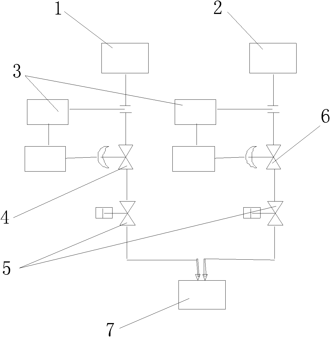
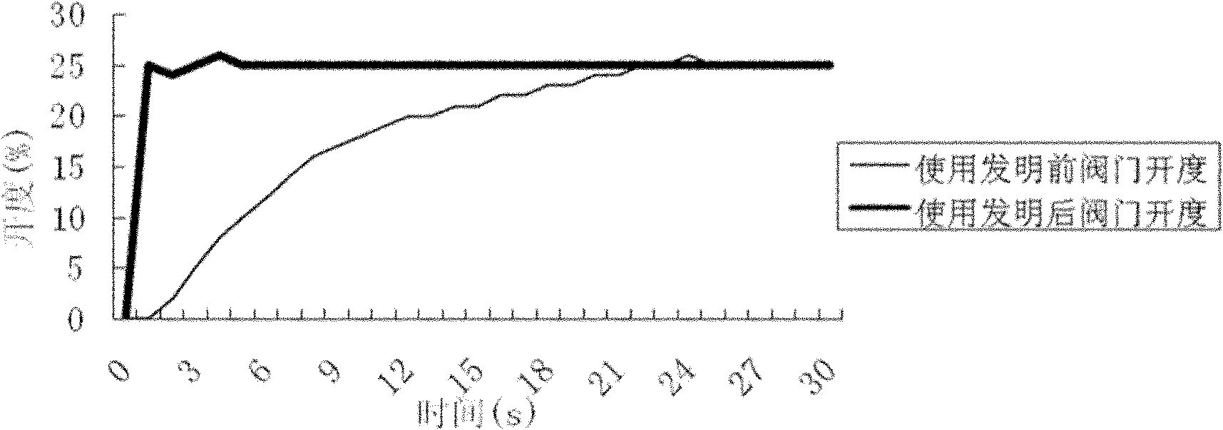
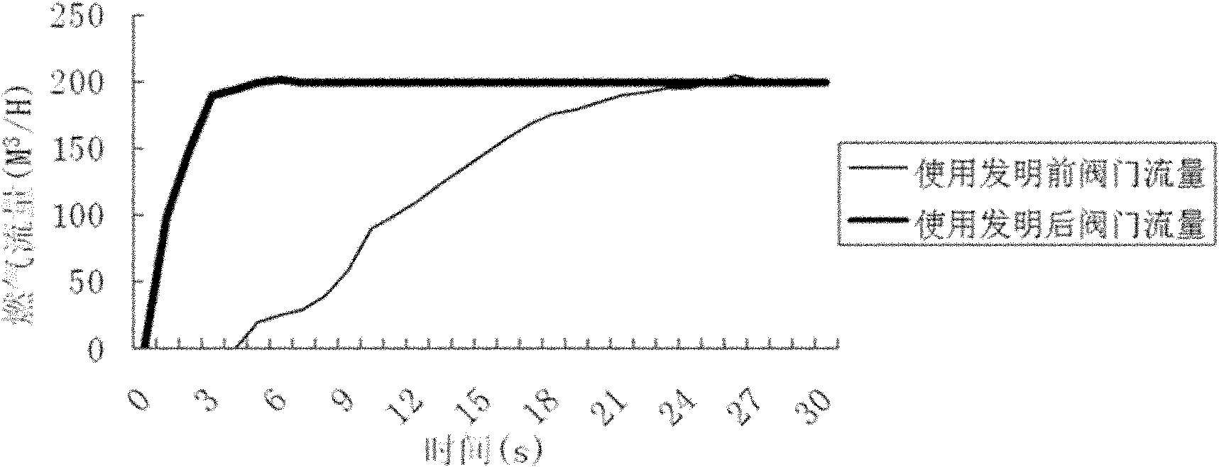
[0027] Taking the galvanized combustion system as an example, the pipe diameter of the gas flow regulating valve 4 is 100mm; the pipe diameter of the air flow regulating valve 6 is 400mm; when the temperature and pressure are stable, the opening of the gas flow regulating valve 4 and the air flow regulating valve 6 Both are 25%, the gas flow under this opening is 200M 3 / H, air flow is 800M 3 / H. Control the combustion system as follows:

[0028] A. Adjust the opening of the gas flow regulating valve 4 and the air flow regulating valve 6 to 25% before combustion, and the gas flow regulating valve 4 and the air flow regulating valve 6 in this process are controlled by the PLC control system.

[0029] B. Carry out combustion and run the PID control system 3. The PID control system 3 uses the gas flow regulating valve 4 and the air flow regulating valve 6 to increase or decrease the fuel and air flow according to the change of the load and working conditions, adjust the tempera...

Embodiment 2

[0032] Taking the combustion system in the heating section of the continuous retreat unit as an example, the diameter of the gas flow regulating valve 4 is 100mm; the pipe diameter of the air flow regulating valve 6 is 400mm; when the temperature and pressure are stable, the gas flow regulating valve 4 and the air flow regulating valve 6 The opening degree is 20%, and the gas flow rate under this opening degree is 150M 3 / H, air flow is 600M 3 / H. Control the combustion system as follows:

[0033] A. Adjust the opening of the gas flow regulating valve 4 and the air flow regulating valve 6 to 16% before combustion, which is 80% of the opening in stability. control system control.

[0034] B. Carry out combustion and run the PID control system 3. The PID control system 3 uses the gas flow regulating valve 4 and the air flow regulating valve 6 to increase or decrease the fuel and air flow according to the change of the load and working conditions, adjust the temperature and th...

Embodiment 3

[0037] Taking the combustion system in the heating section of the continuous retreat unit as an example, the diameter of the gas flow regulating valve 4 is 80mm; the pipe diameter of the air flow regulating valve 6 is 300mm; when the temperature and pressure are stable, the gas flow regulating valve 4 and the air flow regulating valve 6 The opening degree is 30%, and the gas flow rate under this opening degree is 120M 3 / H, air flow is 480M 3 / H. Control the combustion system as follows:

[0038] A. Adjust the opening of the gas flow regulating valve 4 and the air flow regulating valve 6 to 28% before combustion, which is 93.3% of the opening in stability. The gas flow regulating valve 4 and air flow regulating valve 6 in this process are passed through PLC control system control.

[0039]B. Carry out combustion and run the PID control system 3. The PID control system 3 uses the gas flow regulating valve 4 and the air flow regulating valve 6 to increase or decrease the fuel...


PUM


Abstract

The invention discloses a flow control method of a combustion system, in particular relating to the flow control method of the combustion system used in galvanization or a heating section of a continuous annealing unit. The invention provides the flow control method of the combustion system which can help the combustion system reach a stable state rapidly, comprising the following steps: A. firstly measuring opening of a gas flow regulating valve and an air flow regulating valve in the case of stable temperature and pressure; B. setting the opening of the gas flow regulating valve and the air flow regulating valve to be 80%-100% of the opening in the case of stable temperature and pressure before burning for realizing gas combustion at the opening; and C. burning and operating a PID control system which increases or decreases fuel and air flow and adjusts temperature and temperature deviation by the gas flow regulating valve and the air flow regulating valve according to change of load and operating conditions so that the whole combustion process reaches a stable status.

Description

technical field [0001] The invention relates to a combustion system flow control method, in particular to a combustion system flow control method used in the heating section of a galvanizing or continuous annealing unit. Background technique [0002] In the combustion system, PID (proportional-integral-differential controller) is usually used for control. The PID controller adjusts the deviation of the entire control system according to the PID control principle, so that the actual value of the controlled variable is in line with the process requirements. The predetermined value is the same. Although the PID controller can keep the actual value consistent with the process value in the long-term operation, it is difficult to quickly reach the predetermined process value at the beginning. For example, the combustion system in the heating section of the galvanizing or continuous annealing unit, the diameter of the gas and air pipes is usually between 100mm and 200mm according ...

Claims


Application Information

Patent Timeline
Patent Type & Authority Applications(China)
IPC IPC(8): F23N1/02
Inventor 王良兵杨泽猛周兵
Owner PANGANG GROUP VANADIUM TITANIUM & RESOURCES
Why Eureka
Try Eureka