
Detection system of driving plates liquid crystal television and liquid crystal display

A technology of liquid crystal display and LCD TV, which is applied in the direction of static indicators, instruments, measuring electronics, etc., and can solve the problems of lack of uniformity in quality control, low test efficiency, and long time spent

Active Publication Date: 2011-01-19
广东中科芯联智能技术有限公司
View PDF4 Cites 28 Cited by
  • Summary
  • Abstract
  • Description
  • Claims
  • Application Information

AI Technical Summary

Problems solved by technology

[0002] At present, when LCD TV and LCD driver board (also known as the main control board) are tested, the operator manually controls the remote control to switch the channel of the board to be tested. Then the image signal of each channel needs to be connected to the LCD panel Human eyes are used to judge whether the quality of the image output is up to the standard. The sound signal is connected to the earphone to judge whether the sound quality is up to the standard through human ear audition, and a large number of testing instruments are needed to detect the change of voltage and current. All judgments are made by humans. Consciousness is used as the judgment standard, quality control is not uniform, and reliability and stability are not guaranteed. Therefore, the traditional detection method requires the full intervention of the operator in the testing process to complete, and the detection takes a long time, which not only leads to A lot of time, manpower, and material resources are consumed, and the testing efficiency is very low. The testing station has become a serious bottleneck in the output of manufacturers in this industry.

Method used


Image

  • Detection system of driving plates liquid crystal television and liquid crystal display
  • Detection system of driving plates liquid crystal television and liquid crystal display
  • Detection system of driving plates liquid crystal television and liquid crystal display

Examples


Embodiment Construction

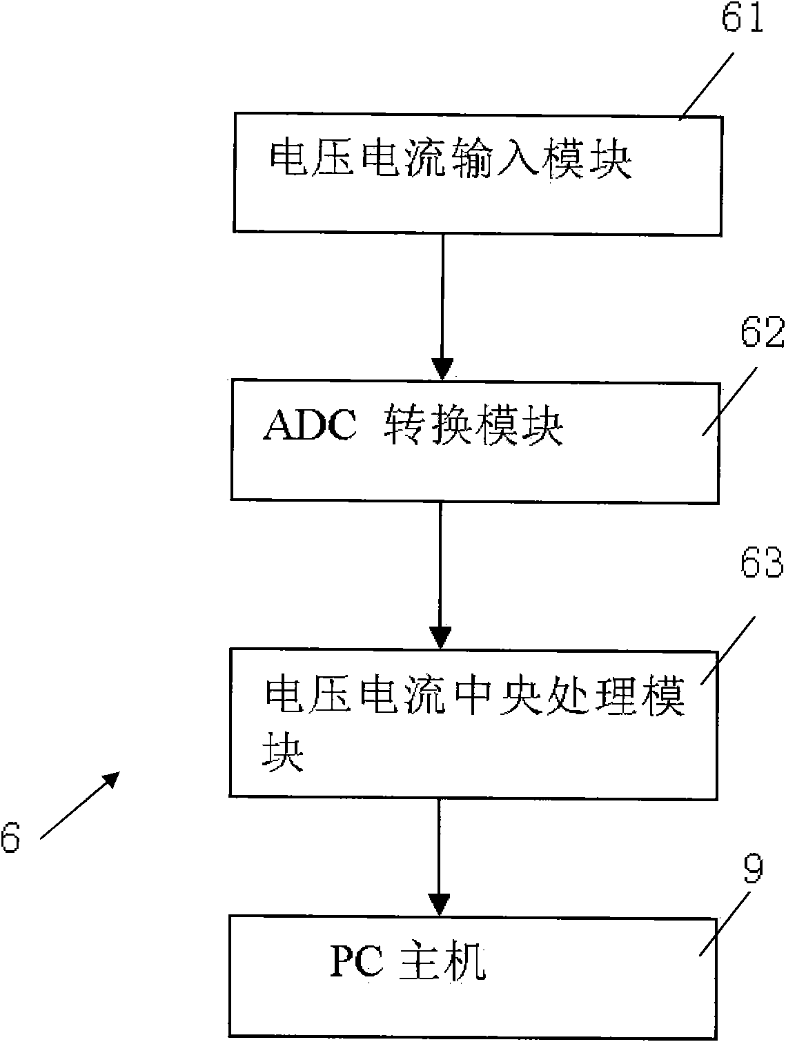
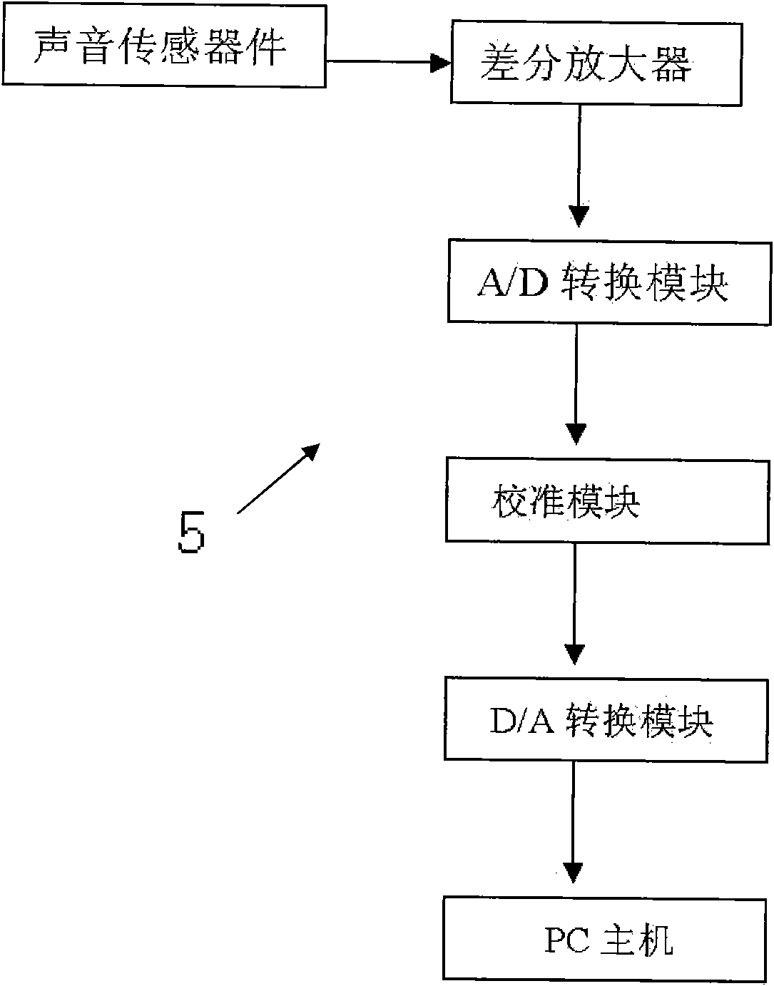
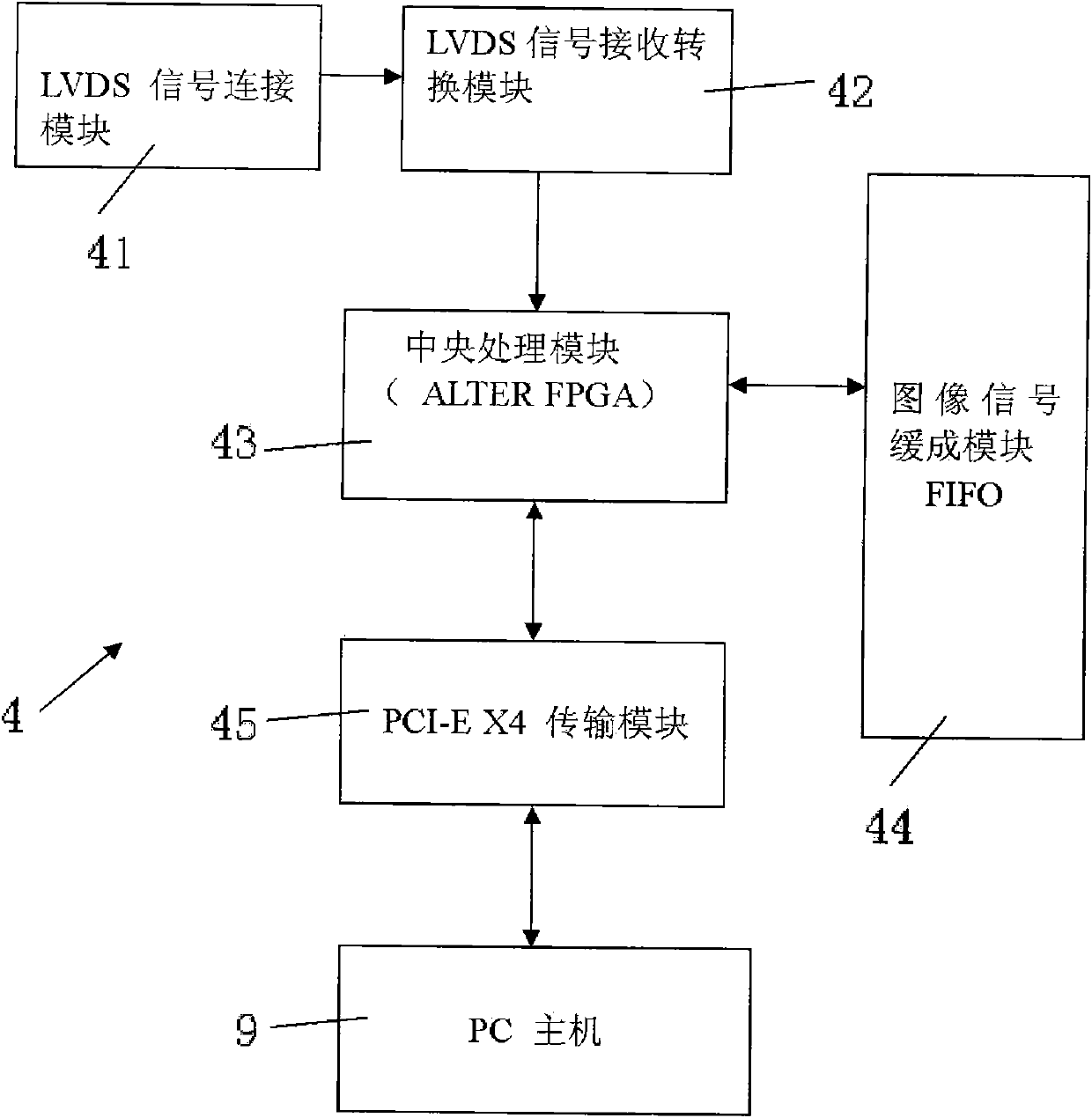
[0059] Example: see Figure 1~7 As shown, the LCD TV and LCD driver board detection system consists of a signal generator 1, a board to be tested 2, a fixing device for the board to be tested 3, an image acquisition component 4, a sound acquisition component 5, a voltage and current analog quantity acquisition component 6, Digital signal acquisition component 7, IO control component 8, PC host 9, system processing software 91 and customer production management system 10.

[0060] The board to be tested 2 is the LCD TV drive board and the LCD drive board;

[0061] Signal generator 1 is used to generate various signals and provide test input signals for the board under test;

[0062] The board-to-be-tested fixing device 3 has a fixture 31 for fixing the board-under-test, electrically connected to the probe 32 of the board-under-test, the board-under-test 2 is clamped on the fixture 31, and one end of the probe 32 electrically connected to the board-under-test is electrically connected...


PUM


Abstract

The invention discloses a detection system of the driving plates of a liquid crystal television and a liquid crystal display. In the invention, a signal generator generates various signals and inputs the signals to a card to be tested; the card to be tested is the driving plate of the liquid crystal television or the liquid crystal display; an image signal acquisition part acquires the LVDS original signals or VGA and DVI original signals of the card to be tested directly to obtain image signals of channels, a sound acquisition part acquires the original sound signals of the channels, a voltage and current analogue value acquisition part acquires an on-board voltage and a current signal to compare the on-board voltage and the current signal with various standard sample data prestored in system processing software of a PC host computer in terms of image, sound, voltage and current signal to generate a test report and a test result; and the test report and the test result are transmitted to a client production management system through a serial port or a network to instruct the client in production without any extra detection device, and thus, the detection cost is reduced greatly.

Description

Technical field: [0001] The invention relates to the technical field of liquid crystal television and liquid crystal display detection, and more specifically to a liquid crystal television and liquid crystal display drive board detection system. Background technique: [0002] At present, when the LCD TV and the LCD driver board (also known as the main control board) are tested, the operator manually controls the remote control to switch the channel of the board to be tested. Then the image signal of each channel needs to be connected to the LCD panel The human eye is used to artificially judge whether the quality of the image output is up to standard. The sound signal is connected to the earphone to judge whether the sound quality is up to the standard by listening to the human ear, and a large number of testing instruments are needed to detect the voltage and current changes. All judgments are human-oriented Consciousness is used as the criterion. There is no uniformity in quali...

Claims


Application Information

Patent Timeline
IPC IPC(8): G09G3/00G01R31/00
Inventor 杨玉峰
Owner 广东中科芯联智能技术有限公司
Features
  • Generate Ideas
  • Intellectual Property
  • Life Sciences
  • Materials
  • Tech Scout
  • Unparalleled Data Quality
  • Higher Quality Content
  • 60% Fewer Hallucinations
Learn More