Energy-efficient type injection molding machine

An injection molding machine, energy-saving technology, applied in the field of mold injection molding machine improvement, can solve problems such as electric energy waste, and achieve the effect of eliminating overflow phenomenon, good use effect and reasonable design

Inactive Publication Date: 2011-01-26
陈志华 +1
View PDF6 Cites 14 Cited by
  • Summary
  • Abstract
  • Description
  • Claims
  • Application Information

AI Technical Summary

Problems solved by technology

This also causes a lot of waste of electric ...

Method used


Image

  • Energy-efficient type injection molding machine
  • Energy-efficient type injection molding machine
  • Energy-efficient type injection molding machine

Examples


Embodiment 1

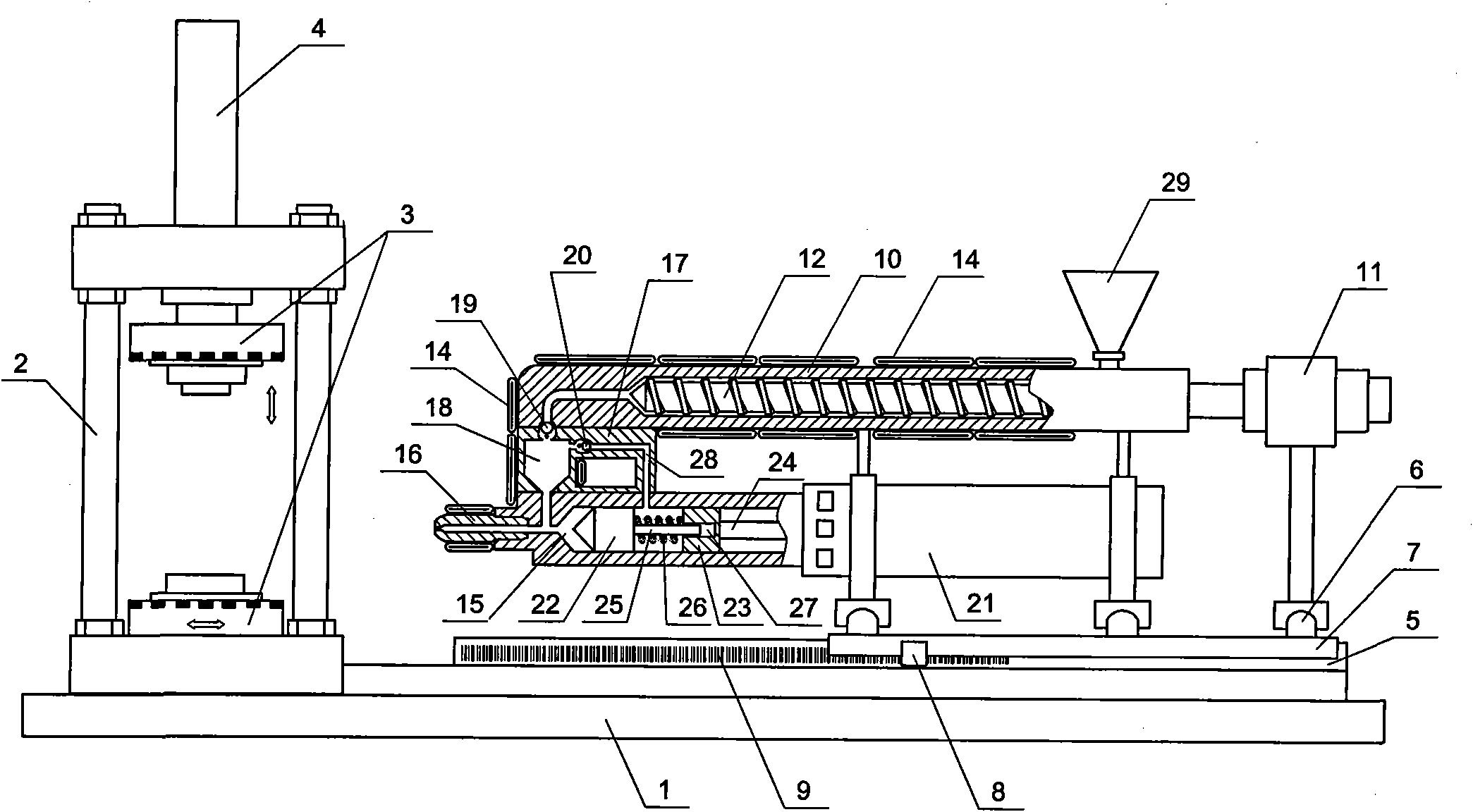
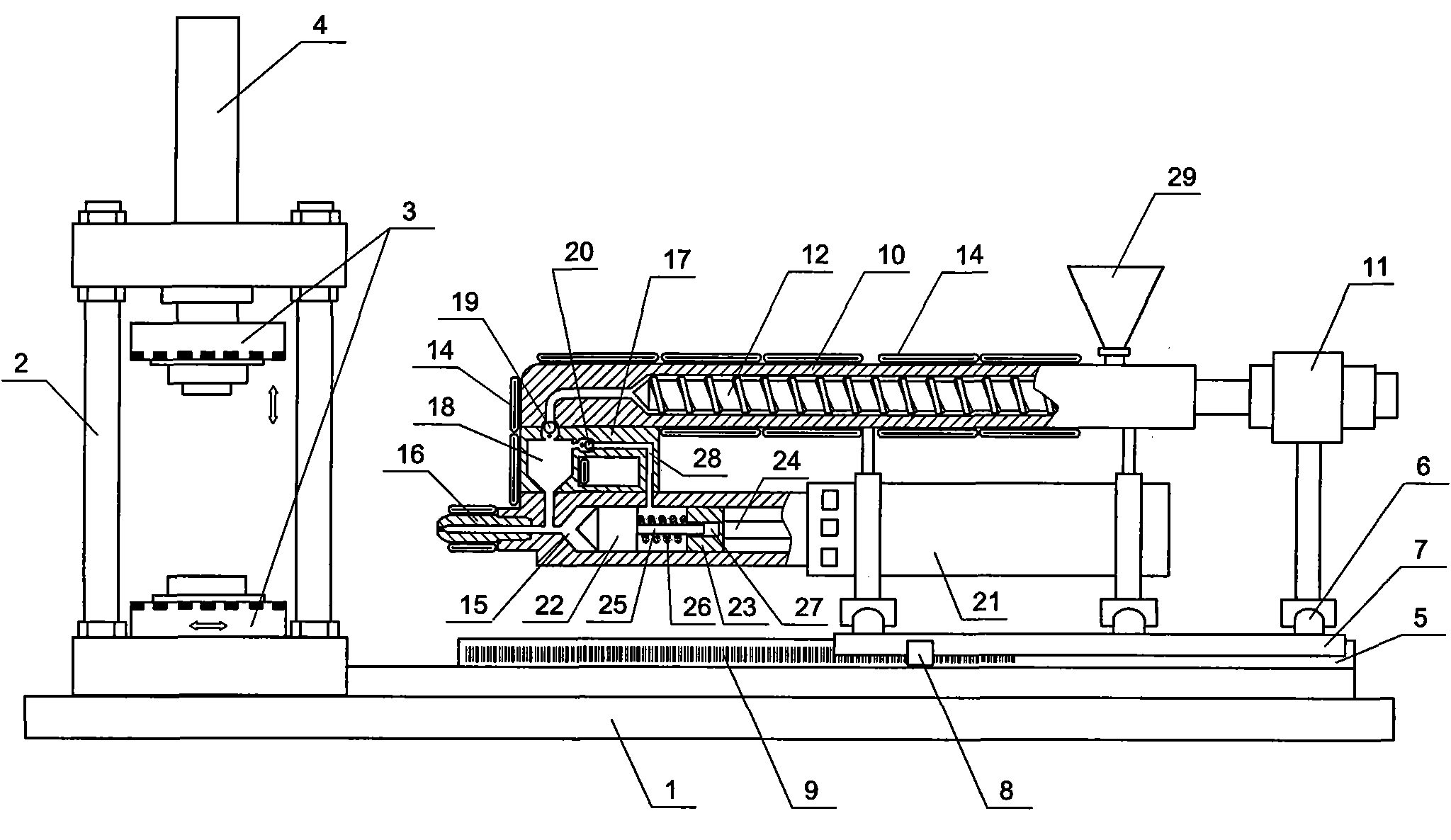
[0024] Embodiment one: see figure 1 , an energy-saving injection molding machine, number 1 is the base, 2 is the vertical mold clamping mechanism bracket, 3 is the mold, 4 is the hydraulic cylinder, 5 is the horizontal guide rail, 6 is the horizontal guide rail, 7 is the support frame, and 8 is the BPS reader Encoder, 9 is the bar code fixed on the guide rail, 10 is the plasticizing barrel, 11 is the driving machine, 12 is the plasticizing screw (screw propulsion shaft), 14 is the heater, 15 is the injection cylinder, 16 is the nozzle valve , 17 is a booster buffer mechanism, 18 is a material storage chamber, 19,20 are check valves, 21 is an oil cylinder, 22 is a front piston, 23 is a rear piston, 24 is a screw rod of a rear piston, and 25 is a screw rod of a front piston, 26 is pressure spring, and 27 is blind hole, and 28 is booster pipe, and 29 hoppers.

[0025] One end of the base 1 is fixed with a vertical mold clamping device, and the other end is fixed with an injectio...

Embodiment 2

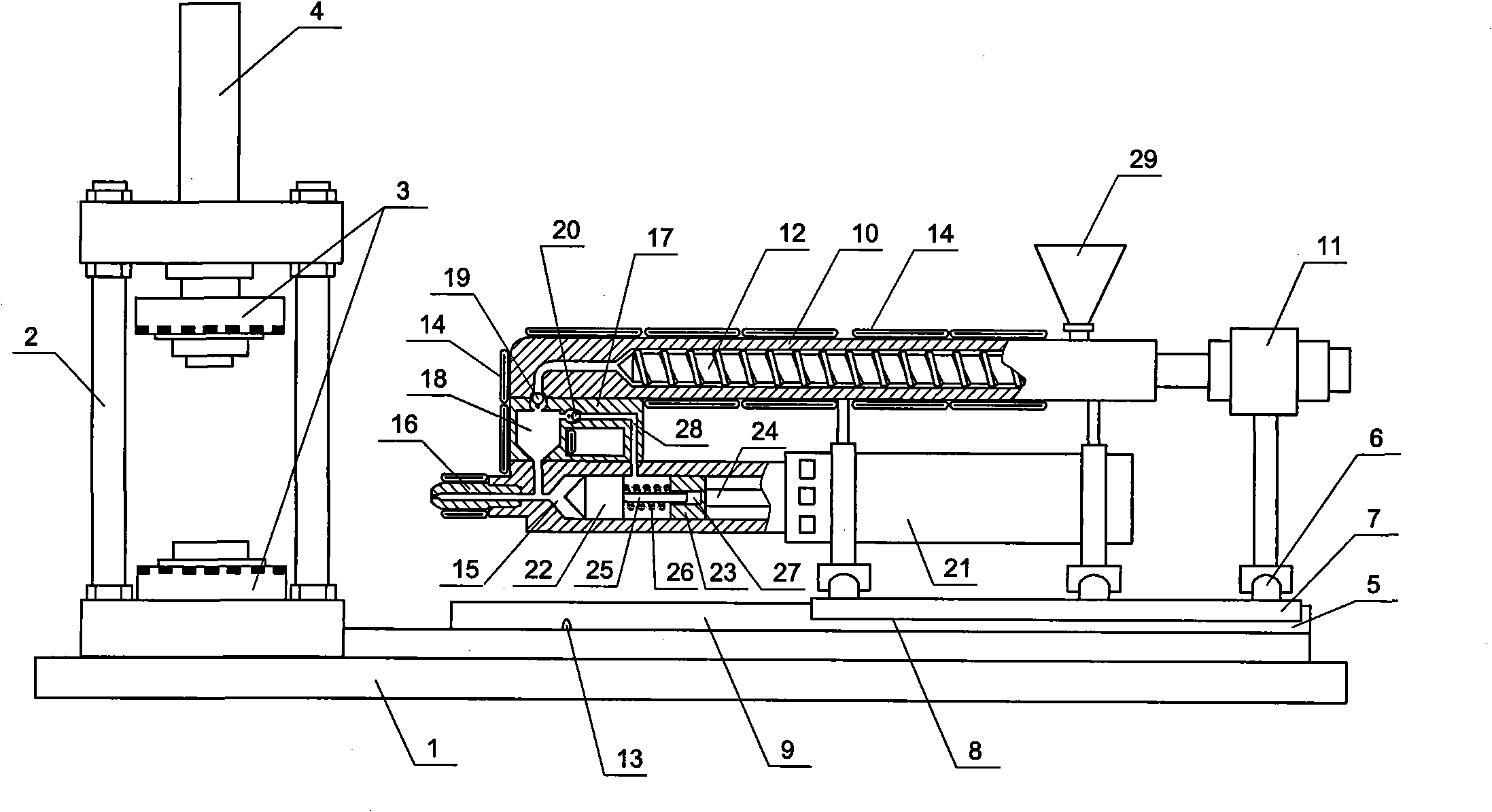
[0033] Embodiment two: see figure 2 , another energy-saving injection molding machine, the content is basically the same as that of Embodiment 1, and the similarities will not be repeated. The difference is that the positioning system is provided with one or more photosensitive elements 13 on the horizontal and / or longitudinal guide rails. , when the material storage extrusion mechanism runs to a specific photosensitive element, the PLC or the host computer determines and controls the output frequency of the frequency converter according to the trigger signal of the photosensitive element.

Embodiment 3

[0034]Embodiment three: the accompanying drawings are not drawn, and the content is basically the same as that of embodiment one, and the similarities will not be repeated. The difference is that the positioning system is installed on the horizontal and / or longitudinal pulley shaft or on a bracket fixed to the pulley shaft There is a laser, and the position of the storage extrusion mechanism is determined by laser distance measurement, and the PLC or the host computer determines and controls the output frequency of the frequency converter according to the laser distance measurement.


PUM


Abstract

The invention relates to an energy-efficient type injection molding machine. A positioning system is arranged on the side of a lateral slipway and/or longitudinal slipway, and a sensing device of the positioning system is connected with a signal input end of a PLC (Programmable Logic Controller) or a host machine. A cylinder motor of the storage extrusion cylinder is connected with a power supply through a frequency converter, a control end of the frequency converter is connected with a control output end of the PLC or the host machine, and the PLC or the host machine controls the frequency converter to output driving signals with corresponding frequencies according to the movement distance of the storage extrusion cylinder on a lateral or longitudinal guide rail. The energy-efficient type injection molding machine enables a system to automatically track the operating state, the operating pressure and the flow signal of the injection molding machine per se, can timely and properly regulate the output flow of a constant delivery pump and can meet the requirements of energy saving. The invention has the advantages of simple structure, reasonable design, good use effect, energy saving and high efficiency and is applicable to popularization and implementation.

Description

1. Technical field: [0001] The invention relates to the improvement technology of a mold injection molding machine, in particular to an energy-saving injection molding machine. 2. Background technology: [0002] When the injection molding machine is processing the product, it usually operates periodically according to the cycle process of mold clamping-injection-holding pressure-cooling-mold opening-ejector-cleaning-re-locking. The working pressure and flow required for each process stage are different, and the load of the oil pump varies greatly throughout the injection molding process, sometimes almost zero (such as the cooling stage). The traditional injection molding machine uses a quantitative pump to supply oil. The oil pump motor is directly energized and runs at a rated speed under power frequency. Therefore, the output flow of the pump cannot change with the change of the load, and it always maintains a constant flow. When the traditional quantitative pump injectio...

Claims


Application Information

Patent Timeline
IPC IPC(8): B29C45/54B29C45/82B29C45/76B29C45/62B29C45/60
Inventor 陈志华张勇张强
Owner 陈志华
Why Eureka
Try Eureka