
Hydraulic chunk with function of compensatory clamping

A hydraulic chuck and piston rod technology, applied in drilling equipment, earthwork drilling, drill pipe, etc., can solve the problems of chuck failure, failure, spring fatigue clamping force, etc., achieve long service life, simple structure, and solve The effect of spring deformation failure

Inactive Publication Date: 2011-01-26
ZHENJIANG ANDA COAL MINE SPECIAL EQUIP
View PDF5 Cites 13 Cited by
  • Summary
  • Abstract
  • Description
  • Claims
  • Application Information

AI Technical Summary

Problems solved by technology

[0003] The spring-clamped hydraulic chuck will gradually decrease with the fatigue of the spring due to the elastic force of the spring, causing the clamping force to fail to meet the requirements
The existing hydraulic chucks for clamping compensation are generally two external oil cylinders parallel to each other. Although the hydraulic compensation of clamping force can be realized, the symmetry of the installation of the oil cylinders, the synchronization of the hydraulic cylinders, and the identity of the extension length of the oil cylinders etc. will cause the oil cylinder to stretch out out of sync and cause partial load, which will cause bearing damage and make the chuck invalid.
[0004] The hydraulically clamped chuck uses hydraulic oil to cause the rubber sleeve to shrink radially to achieve clamping. When the torque is large or impacted, there will be relative rotation between the rubber sleeve and the slips, and the rubber sleeve is easy to wear. In addition, the slag Loading into slips and sleeve assembly can cause sleeve breakage and chuck failure
In addition, due to the safety setting requirements of the drilling rig, when using a hydraulically clamped chuck, it must be equipped with a spring clamped clamp, and the spring of the clamp also has the problems of fatigue and clamping force drop

Method used


Image

  • Hydraulic chunk with function of compensatory clamping
  • Hydraulic chunk with function of compensatory clamping

Examples


Embodiment Construction

[0016] The embodiments of the present invention are described in detail below. This embodiment is implemented on the premise of the technical solution of the present invention, and detailed implementation methods and specific operating procedures are provided, but the protection scope of the present invention is not limited to the following implementation example.

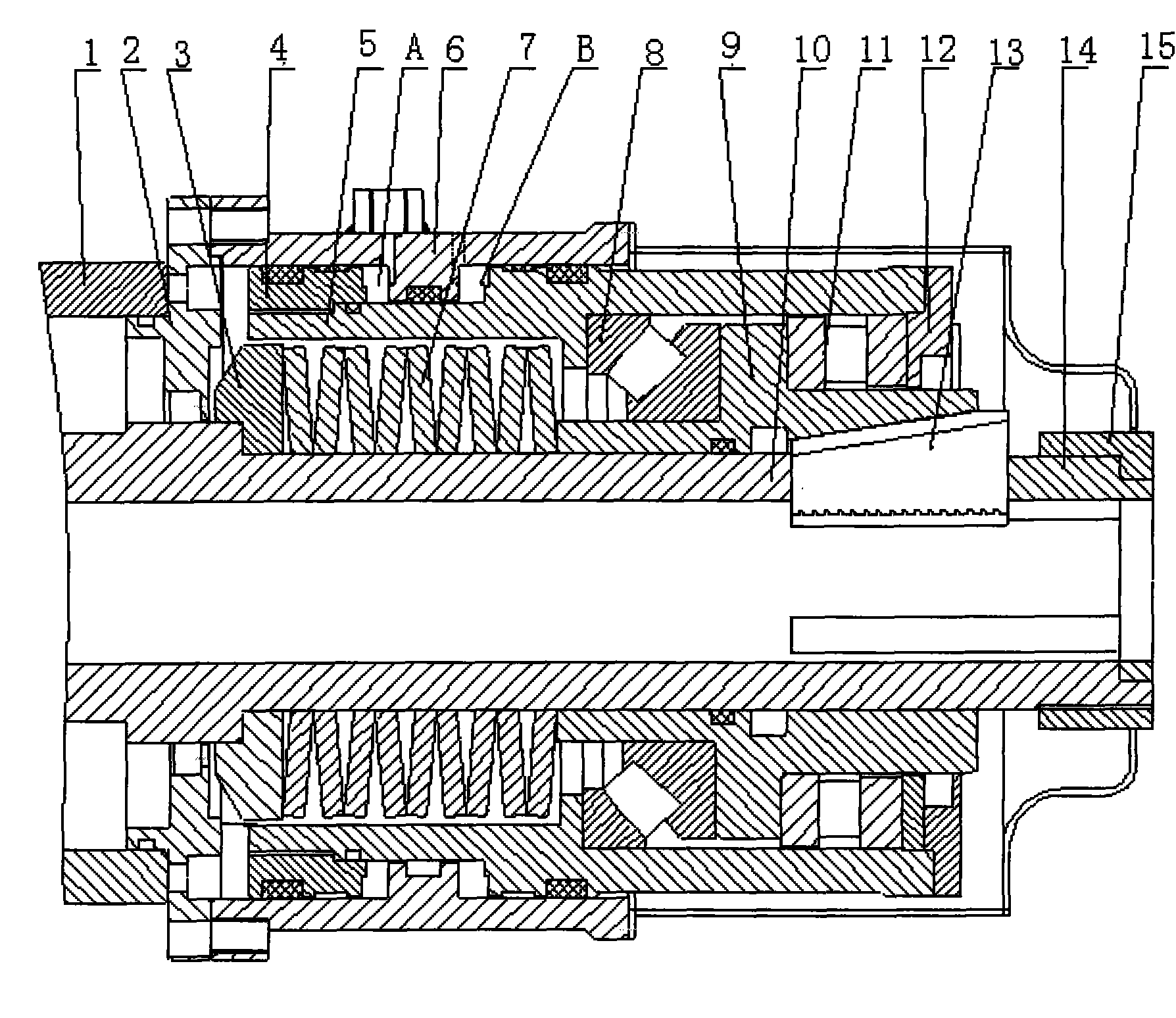
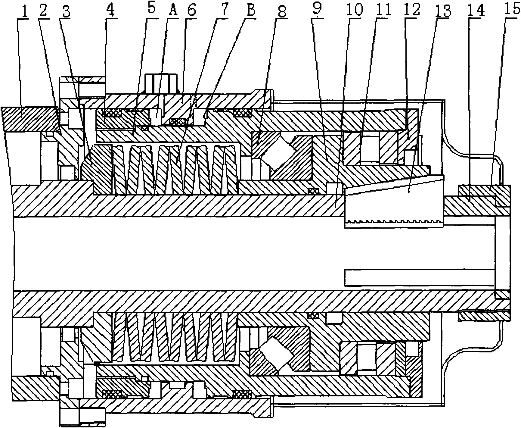
[0017] As shown in the drawings, this embodiment includes a box body 1, a connecting cover 2, a spring seat 3, a piston 4, a hollow piston rod 5, a cylinder barrel 6, a disc spring 7, a self-aligning roller bearing 8, and a slip sleeve 9 , main shaft 10, thrust bearing 11 and slips 13, wherein: the piston rod 5 and the piston 4 are sleeved in the cylinder 6, the piston 4 is fixed on the top of the piston rod 5, the connecting cover 2 and the cylinder 6 are fixedly connected, and the disc spring One end of 7 is located on the shoulder of the main shaft 10, the other end is located on the slip sleeve 9, the slip slee...


PUM


Abstract

The invention discloses a hydraulic chunk with function of compensatory clamping, which comprises a piston, a hollow piston rod, a cylinder barrel, a connecting cover, a disc spring, a aligning roller bearing, a slip sleeve, a main shaft, a thrust bearing and a slip. The piston rod and the piston are sleeved in the cylinder barrel, the piston is fixed at the top end of the piston rod, the connection cover and the cylinder barrel are fixedly connected, one end of the disc spring is positioned on the shaft shoulder of the main shaft and the other end is positioned on the slip sleeve, the slip sleeve is arranged at the hollow part of the piston rod and is sleeved on the main shaft, a bearing positioning ring is arranged in the middle of the slip sleeve, the aligning roller bearing and the thrust bearing are respectively arranged at the two ends of the bearing positioning ring on the slip sleeve and positioned at the hollow part of the piston rod, and the slip is arranged in the slip sleeve. By the invention, the requirement of a high-torque drilling machine on great clamp force is met; a ring-shaped double-acting oil cylinder is used for auxiliary clamping so that a problem on deformation failure of a spring can be solved; and hydraulic pressure can be converted into clamping force by utilizing a cavity among the hydraulic cylinder barrel, the piston and the piston rod. The invention has the advantages of simple structure and long service life.

Description

technical field [0001] The invention relates to a hydraulic chuck for a drilling machine, in particular to a hydraulic chuck capable of compensating clamping. Background technique [0002] The hydraulic chuck is an important working part for clamping the drill pipe when the drilling rig is working, and transmitting torque to realize the rotary cutting and drilling of the drill bit. The reliability of clamping is the key to the normal operation of the drilling rig. At present, the hydraulic chucks of existing domestic drilling rigs include: spring force clamping, hydraulic pressure release (clamping is normal); hydraulic clamping, spring force release (releasing is normal); hydraulic clamping, loosening type. [0003] The spring-clamped hydraulic chuck will gradually decrease with the fatigue of the spring due to the elastic force of the spring, so that the clamping force cannot meet the requirements and fail. The existing hydraulic chucks for clamping compensation are gener...

Claims


Application Information

Patent Timeline
IPC IPC(8): E21B19/10
Inventor 邢苏宁孔伟
Owner ZHENJIANG ANDA COAL MINE SPECIAL EQUIP
Learn More