Heat exchanger and refrigerating cycle device provided with same

A technology of heat exchangers and heat transfer tubes, applied in heat exchange equipment, lighting and heating equipment, evaporators/condensers, etc., can solve problems such as reduced device performance, reduced heat exchange volume, and reduced device performance.

Active Publication Date: 2012-07-18
MITSUBISHI ELECTRIC CORP
View PDF1 Cites 0 Cited by
  • Summary
  • Abstract
  • Description
  • Claims
  • Application Information

AI Technical Summary

Problems solved by technology

[0003] If frost forms on the surface of the fin, as the frost becomes thicker, the thermal resistance of the surface of the fin increases, and as a result, the amount of heat exchange with the air decreases, and the performance of the device decreases
[0004] Due to the growth of frost, the fins are blocked, the resistance of the wind path increases, and the performance of the device is greatly reduced
[0005] In addition, in order to remove the frost attached to the surface of the fins, the device must be defrosted periodically, which also greatly reduces the performance of the device.

Method used


Image

  • Heat exchanger and refrigerating cycle device provided with same
  • Heat exchanger and refrigerating cycle device provided with same
  • Heat exchanger and refrigerating cycle device provided with same

Examples


Embodiment approach 1

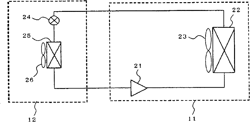
[0035] Embodiment 1 of the heat exchanger of the present invention will be described with reference to the drawings by taking a refrigeration cycle apparatus using the heat exchanger as an example. figure 1 Indicates the refrigerant circuit of a refrigeration unit. This refrigerating device is used for indoor refrigerating by performing a vapor compression type refrigerating cycle operation. exist figure 1 Among them, 11 is an outdoor unit, and 12 is an indoor unit. The outdoor unit 11 includes a compressor 21 , a condenser 22 , and a condenser fan 23 that sends air to the condenser 22 . The indoor unit 12 includes an expansion mechanism 24 , an evaporator 25 , and an evaporator fan 26 that sends air to the evaporator 25 . The compressor 21, the condenser 22, the expansion mechanism 24, and the evaporator 25 constitute a refrigerating cycle, and the inside thereof is filled with a refrigerant for circulation. The present invention is mainly found in the forms of low-temp...

Embodiment approach 2

[0059] Next, the heat exchanger according to Embodiment 2 of the present invention will be described. Figure 8 The fins 71 and the heat transfer tubes 72 constituting the evaporator (heat exchanger) 25 are shown. As described above, the condenser (heat exchanger) 25 absorbs heat by vaporizing the liquid refrigerant flowing through the heat transfer tubes 72 , and exchanges heat with the outside air through the fins 71 . As described above, under freezing conditions, the temperature of the surrounding air is -20°C, the evaporation temperature is about -30°C, and the surface of the fin 71 is below 0°C, and frost is formed. Additionally, if Figure 8 As shown, around the heat transfer tube 72, even on the surface of the fin 71, the temperature is particularly low. In Embodiment 2, holes 73 for lowering the freezing point of condensed water droplets are provided by using the Gibbs-Thomson effect of the following formulas (5) and (6) around the entire fins 71 or heat transfer tu...

Embodiment approach 3

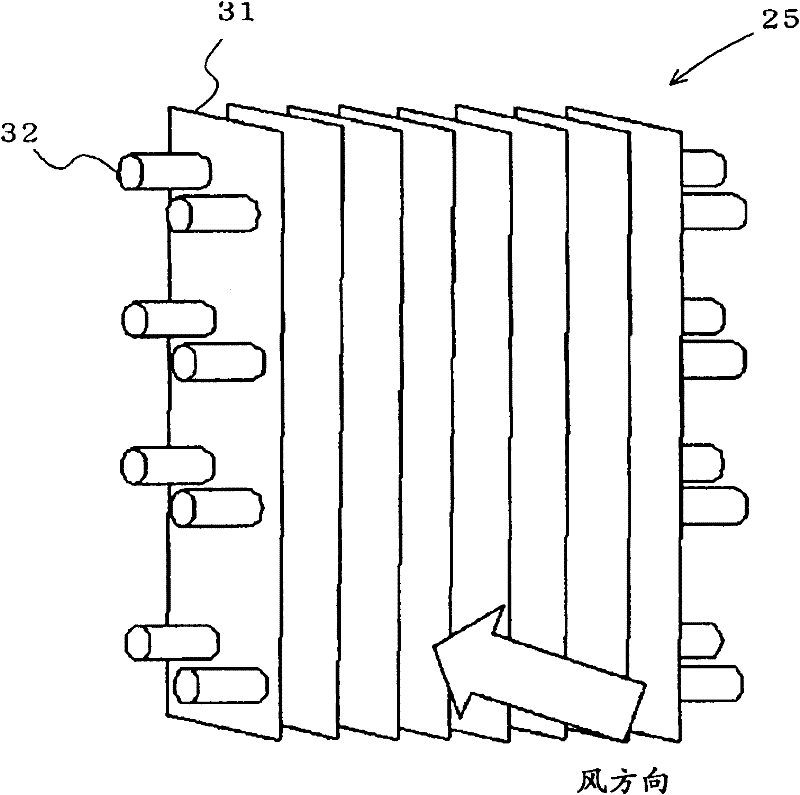
[0072] Next, the configuration of Embodiment 3 of the present invention will be described. Figure 11 An example of a well-known structure of an evaporator (heat exchanger) is shown. In this evaporator (heat exchanger), a plurality of fins 31 are arranged in parallel at regular intervals, and heat transfer tubes 32 pass through the fins 31 . In such a heat exchanger, the fins 31 are cooled to 0° C. or lower, and when frost starts to form, frost grows from both surfaces of the fins 31 facing each other. After a certain period of time, the space between the fins 31 is blocked by frost, the fins 31 are buried, and the performance of the evaporator decreases. For this purpose, the evaporator is defrosted to melt the frost between the fins 31 . The general defrosting method is to switch the four-way valve to reverse the flow of refrigerant, change the evaporator heat exchanger and condenser heat exchanger, and melt the frost.

[0073] Compared with the conventional fins in which...


PUM


Abstract

In an outdoor machine in a cold district and an indoor machine of a refrigerator, a heat exchanger acting as an evaporator is cooled to an air dew-point temperature or below. When the temperature is 0 DEG C or below, frost is formed on the surface of the heat exchanger. The frost formation causes an increase in air duct resistance and heat resistance, and leads to the lowering of the performance of the device. However, if the frost formation is delayed, energy can be saved. Therefore, a plurality of holes such as a plurality of holes with a radius of several nano-orders are formed in the surfaces of the fins of the heat exchanger to suppress the occurrence of condensed water droplets produced on the surfaces of the fins. Also, a plurality of holes for causing the Gibbs-Thomson effect are formed to lower the freezing point for delaying the lowering of the performance due to frost formation.

Description

technical field [0001] The present invention relates to a heat exchanger installed in air conditioners, low-temperature equipment, water heaters, etc. to exchange heat with air. In particular, it relates to the technology of providing a plurality of holes on the heat transfer surface of the fins (radiation fins) constituting the heat exchanger to conduct heat with the air to control the area and the temperature of frost formation on the heat transfer surface, even if the frost is transmitted When frost forms on the hot surface, the time until the air passage is blocked can also be delayed, and the performance of the device can be maintained for a longer period of time. Background technique [0002] In the conventional refrigeration cycle system, if the surface temperature of the fins constituting the heat transfer surface of the heat exchanger used falls below 0°C, the water vapor in the air will become condensed water droplets on the surface of the fins, and then cool down ...

Claims


Application Information

Patent Timeline
Patent Type & Authority Patents(China)
IPC IPC(8): F28F1/32
CPCF28F1/32F25B47/006F28F13/187F25B39/022F25B2500/01
Inventor 田代雄亮滨田守亩崎史武前川武之森本裕之山下浩司
Owner MITSUBISHI ELECTRIC CORP
Why Eureka
Try Eureka