Spherical target ceramic neutron tube and manufacturing method thereof

A technology of neutron tubes and ceramics, which is applied in the field of electronic device structure, can solve the problems of easy short circuit and insufficient convergence of ion beams, and achieve the problems of insufficient axial magnetic field, improvement of proton ratio of extracted beam, and increase of target area Effect

Inactive Publication Date: 2011-02-02
CHANGCHUN ZHIFANGDA TECH
View PDF5 Cites 9 Cited by
  • Summary
  • Abstract
  • Description
  • Claims
  • Application Information

AI Technical Summary

Problems solved by technology

[0003] The invention discloses a ceramic neutron tube with a spherical target, which solves the problem of insufficient ion

Method used


Image

  • Spherical target ceramic neutron tube and manufacturing method thereof
  • Spherical target ceramic neutron tube and manufacturing method thereof

Examples


Embodiment 1

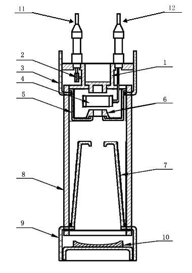
[0014] according to figure 1 As shown, the body of the neutron tube of the present invention consists of an upper envelope 3, a ceramic shell 8, and a lower envelope 9 to form a closed circular axisymmetric structure, and the target 10 is fixed on the inside of the lower envelope 9 and is packaged at the bottom of the ceramic shell 8; The frame 1 is provided with a high-voltage electrode 12 and a storage electrode 11 fixed on the upper port of the ceramic shell 8 through the upper cover 3, and the ceramic shell 8 is provided with an acceleration cylinder 7; the anode cylinder 4 is arranged on the ion source cover 5 and the electrode frame 1 Between, and connected with the high-voltage electrode 12; The reservoir 2 is set in the frame of the electrode holder 1 and connected with the electrode 11 of the reservoir; The ion source cover 5 is arranged in the upper port of the ceramic shell 8, and the magnetic material ring 6 is outsourced and can be installed with a valve plate In ...

Embodiment 2

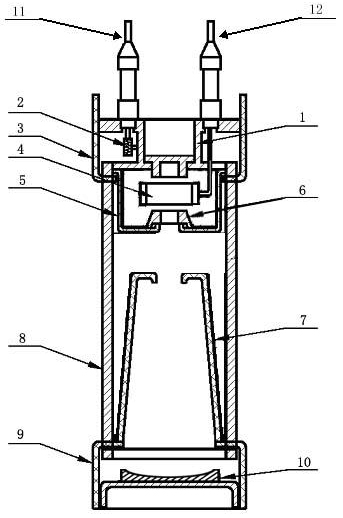
[0016] In the structure of Embodiment 1, the shape of the end of the target 10 of the neutron tube can be made into a spherical shape, and the center of the spherical surface is coaxial with the central hole of the accelerating tube 7 .

[0017] Taking the Φ50 neutron tube as an example, after improvement, the service life is increased by more than 2 times, the output is increased by about 3 times, the stability is not more than 3%, and the yield is higher than 90%.

Embodiment 3

[0019] The electrode frame 1 and the target 10 are manufactured, the electrode frame 1 is provided with a high-voltage electrode 12 and a storage electrode 11 fixed on the upper port of the ceramic shell 8 through the upper cover 3, and the shape of the end of the target 10 is made into a spherical shape R=25mm, The center of the sphere is taken as the center hole center of the acceleration tube 7; then the upper cover 3, the ion source cover 5, the magnetic material ring (NdFeB permanent magnet material) 6 are outpacked with kovar, the acceleration tube 7, and the lower cover 9 Sealed together with the ceramic shell 8 to ensure that the aperture of the magnetic material ring 6 is the same as the aperture of the ion source cover 5 lead-out hole; then the storage 2, the anode cylinder 4 and the electrode frame 1 are welded together and put into the upper cover 3; the upper edge of the electrode frame 1 and the edge of the upper cover 3, the lower edge of the spherical target 10 ...


PUM


Abstract

The invention discloses a spherical target ceramic neutron tube and a manufacturing method thereof. A magnetic material ring is embedded in the lead-out end of a neutron tube ion source; after the neutron tube is sealed, the magnetic material ring is magnetized; the lead-out end of the neutron tube ion source is embedded with the magnetic material ring, and the magnetic field intensity of the lead-out electrode of the neutron tube reaches 2300 Gs; the beam current density is improved by 11.6% so as to solve the problem of insufficient lead-out end axial magnetic field of the ion source; and the shape of a target end is made into a spherical shape to double the effective target area and increase the radiating area of the target. The lead-out beam flow proton ratio of the neutron tube is greatly improved; under the condition of invariable section surface, the invention improves the target area of nuclear reaction, strengthens the cooling efficiency, greatly lowers neutron tube discharge and breakdown probability and improves the yield (by 0.7 time), the service life and the stability of the neutron tube.

Description

technical field [0001] The invention relates to the improvement of the neutron tube structure, in particular discloses a spherical target ceramic neutron tube and a manufacturing method of the neutron tube, belonging to the technical field of electronic device structures. Background technique [0002] At present, the known ceramic self-targeting neutron tube is composed of a copper head, a storage tank, an upper mask, an anode cylinder, an ion source cover, a ceramic shell, an accelerating cylinder, a lower mask, and a target. After applying a voltage of several thousand volts to the anode cylinder, turn on the low-voltage power supply of the storage, heat the storage, release the deuterium-tritium mixed gas in the storage, ionize into deuterium-tritium ions in the ion source, and then add The negative high voltage of tens of thousands of volts to hundreds of thousands of volts draws out deuterium-tritium ions and accelerates the bombardment to the target, generating 14 Mev...

Claims


Application Information

Patent Timeline
IPC IPC(8): H05H3/06
Inventor 乔双严长春景士伟刘太辉吴猛
Owner CHANGCHUN ZHIFANGDA TECH
Why Eureka
Try Eureka