
Bus voltage stabilization control device
A technology for stabilizing control device and bus voltage, applied in output power conversion devices, electrical components, single-network parallel feeding arrangements, etc., can solve problems such as reducing system efficiency, increasing circuit complexity, and unable to completely eliminate capacitive bias voltage. , to improve control efficiency, reduce the impact of grid voltage fluctuations, and stabilize photovoltaic inverter control.
Patent Information
- Authority / Receiving Office
- CN · China
- Patent Type
- Applications(China)
- Current Assignee / Owner
- Publication Date
- 2011-02-09
- Estimated Expiration
- Not applicable · inactive patent
Smart Images
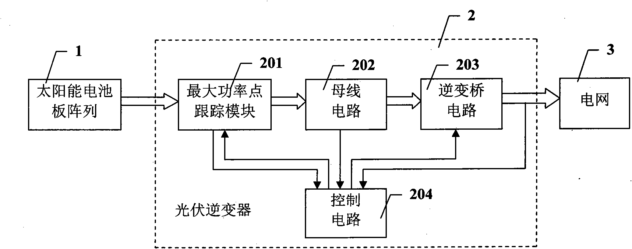
Figure 1 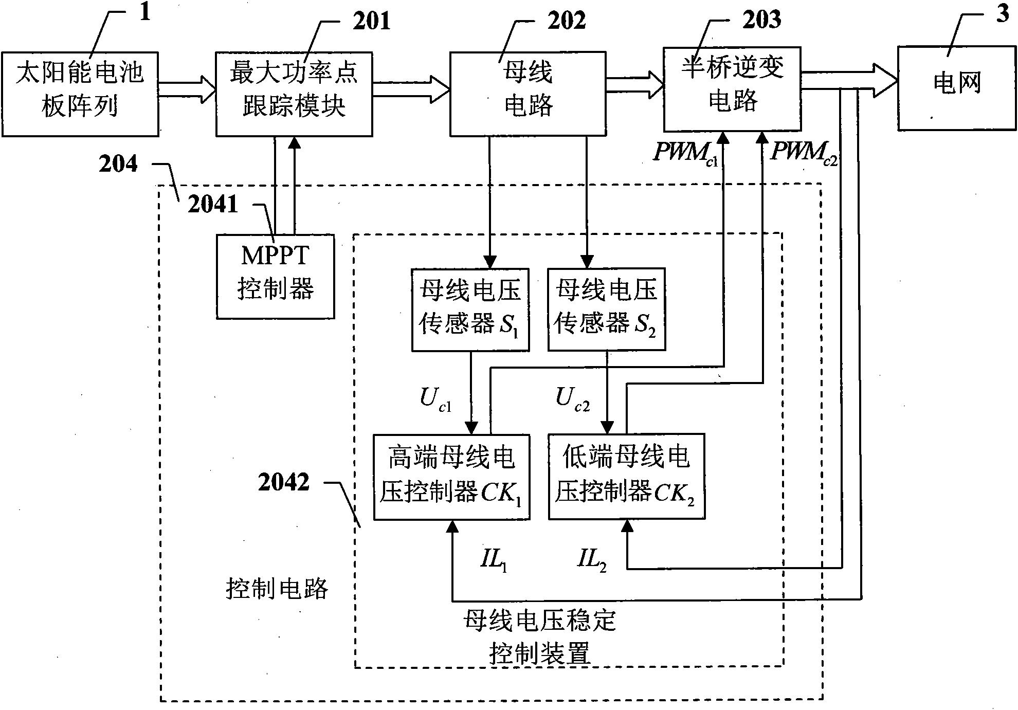
Figure 2 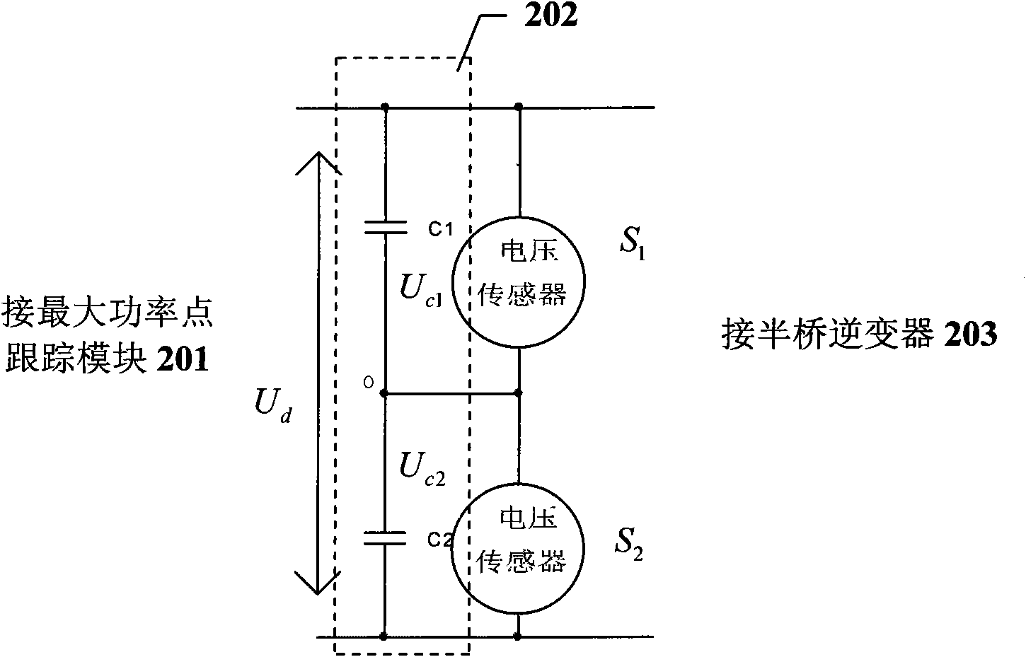
Figure 3
Abstract
Description
technical field
[0001] The invention belongs to the technical field of photovoltaic inverter grid-connected power generation systems, and more specifically relates to a bus voltage stabilization control device for controlling the bus voltage of a photovoltaic inverter. Background technique
[0002] At present, the solar photovoltaic inverter power generation system has been paid attention to by many countries in the world, and the photovoltaic inverter, as a key part of the photovoltaic inverter grid-connected power generation system, has also been greatly developed. Usually, as figure 1 As shown, the photovoltaic inverter grid-connected power generation system is composed of a solar panel array 1 and a photovoltaic inverter 2 . Among them, the photovoltaic inverter 2 includes a maximum power point tracking (MPPT) module 201 , a bus circuit 202 , an inverter bridge circuit 203 and a control circuit 204 , and its function is to convert solar energy into electrical energy and...
Examples
Embodiment
[0026] figure 2 It is a functional block diagram of the bus voltage stabilization control device of the present invention.
[0027] In this example, if figure 2 As shown, the bus voltage stabilization control device 2041 is located in the control circuit 204, including two bus voltage sensors S 1 , S 2 And high and low bus voltage controller CK 1 、CK 2 .
[0028] Two busbar voltage sensors S 1 , S 2 Sampling is performed at a sampling frequency of 100Hz / N, where N is an integer greater than or equal to 1, and the sampling value of the high and low end capacitor voltage of the bus is obtained Then output to the high and low bus voltage controller CK respectively 1 、CK 2 .
[0029] High and low bus voltage controller CK 1 、CK 2 The input of is respectively the sampling value of the high and low end capacitor voltage of the bus bar The output is a pulse width modulation signal for controlling the positive and negative half-period power switches in the half-bridge...