Modular construction camshaft adjuster with a chain or belt wheel

A camshaft adjuster, modular technology for belts/chains/gears, components with teeth, machines/engines, etc., to solve problems such as deformation, damage to camshaft drives, damage to motors, etc.

Inactive Publication Date: 2011-02-09
SCHAEFFLER TECH AG & CO KG
View PDF2 Cites 0 Cited by
  • Summary
  • Abstract
  • Description
  • Claims
  • Application Information

AI Technical Summary

Problems solved by technology

The solid wall thickness X of the cylindrical wheel wall of DE 103 03 991 A1 increases the weight of the sprocket or pulley and thus disadvantageously increases the total mass of the camshaft drive and the sprocket or pulley
[0005] Pot sprockets or pulleys of lower quality have a correspondingly limited stability and can deform under high loads from the driven chain or belt, which can damage the camshaft drive and thus the motor

Method used


Image

  • Modular construction camshaft adjuster with a chain or belt wheel
  • Modular construction camshaft adjuster with a chain or belt wheel
  • Modular construction camshaft adjuster with a chain or belt wheel

Examples


Embodiment Construction

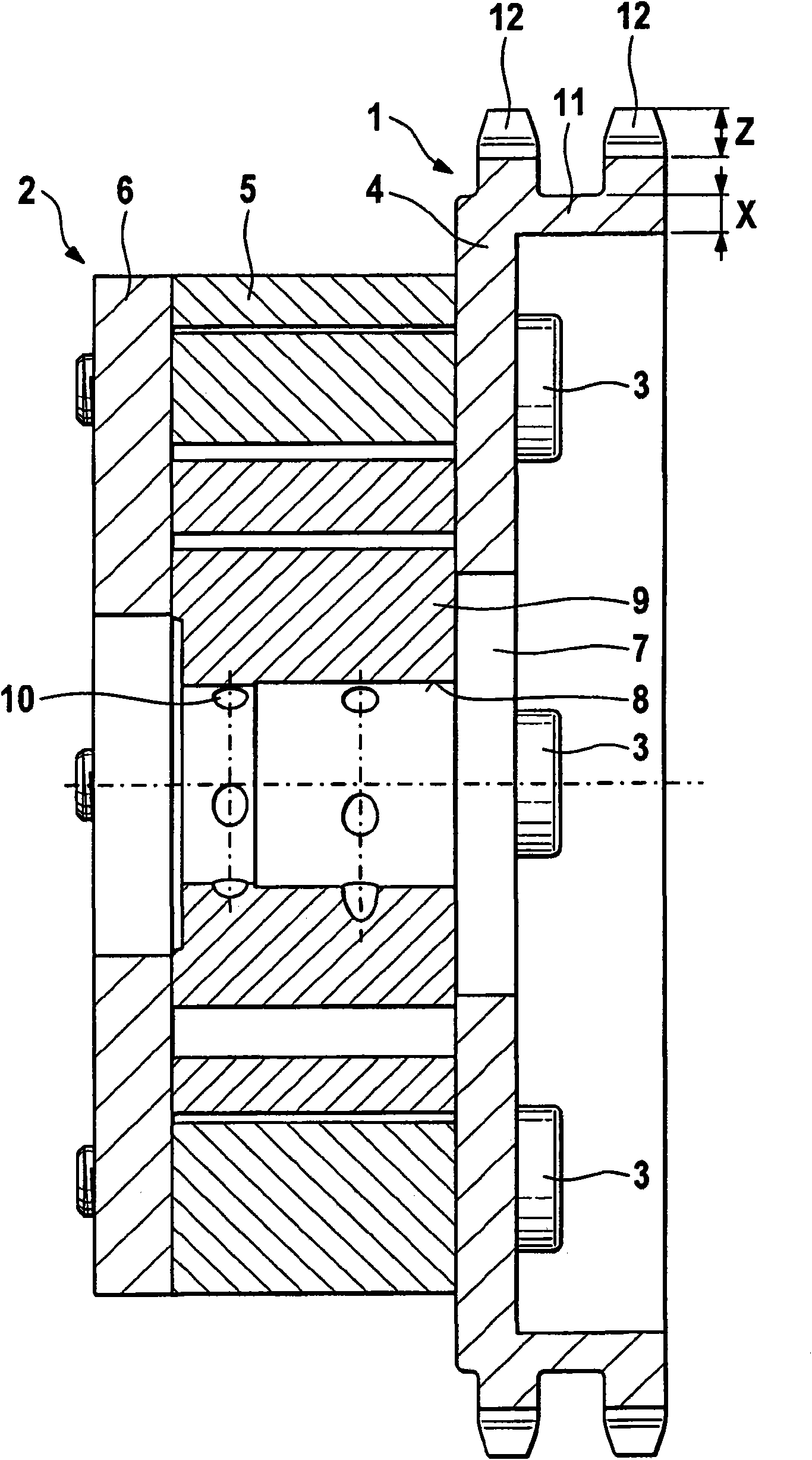
[0017] figure 1 Shown: A pot sprocket 1 made of lightweight material such as aluminum is passed coaxially through the annular gurney 4 of the pot sprocket 1 , the stator 5 and the end of the camshaft adjuster 2 by means of radially uniformly distributed bolts 3 The cover 6 is attached to the modular steel camshaft adjuster 2 of the internal combustion engine (not shown). The central circular opening 7 in the ring gurney 4 is used to accommodate a camshaft (not shown) on which the chain wheel 1 is rotatably mounted via the camshaft adjuster 2 . The bearing structure 8 of the camshaft has lubricant holes 10 in the rotor 9 of the camshaft adjuster 2 .

[0018] On the outer circumference of the annular gurney 4 , essentially axially—away from the camshaft adjuster 2—the outer, substantially cylindrical wheel wall 11 of the pot sprocket 1 protrudes. In the protruding region of the wheel wall 11 of wall thickness X are arranged radially outwardly directed two wheel rims 12 each w...


PUM


Abstract

The invention relates to a modular construction camshaft adjuster (2) for the camshaft drive of an internal combustion engine with a chain or belt wheel (1), comprising at least one wheel rim (12) facing radially outwards with tooth engagement recesses Z, an annular wheel plate (4) around a central circular opening (7) and an essentially cylindrical wheel wall (11) with a wall thickness X, projecting in an axial direction from the annular wheel plate (4), such that the wheel wall(11) and the wheel plate (4) together form a cup shape. The minimum wall thickness X of the essentially cylindricalwheel wall (11) beneath the at least one wheel (12) is equal to half the tooth engagement recess Z and the cup-shaped chain or belt wheel (1) is made from a lightweight material.

Description

technical field [0001] The invention relates to a camshaft adjuster of modular construction with sprockets or pulleys for a camshaft drive of an internal combustion engine, which camshaft adjuster has the features of the preamble of claim 1 . [0002] The camshaft of the internal combustion engine is usually driven by the crankshaft via a chain or toothed belt and is adjusted continuously in a closed control loop, wherein a typical adjustment range is a crank angle of 40° to 60°. The crank angle to be adjusted is stored in the characteristic curve cluster. The adjustment takes place eg hydraulically, via electrically operated control valves fed from the oil circuit, and an optimized valve adjustment time is achieved via the parameters motor load and motor speed. Depending on the motor design and the number of regulators, significant reductions in fuel consumption and exhaust emissions as well as increases in power and torque can be achieved. Background technique [0003] A...

Claims


Application Information

Patent Timeline
Patent Type & Authority Applications(China)
IPC IPC(8): F01L1/344F16H55/06
CPCF01L1/3442F01L2101/00F01L2103/00F01L2301/00F01L2303/00
Inventor 约阿希姆·迪茨安德烈亚斯·施特劳斯
Owner SCHAEFFLER TECH AG & CO KG
Why Eureka
Try Eureka