Measuring method and device for characterizing a semiconductor component

A technology of measuring device and measuring method, which is applied in the direction of single semiconductor device testing, measuring device, measuring electricity, etc., to achieve the effect of low equipment cost and simplified analysis and processing

Active Publication Date: 2014-11-26
FRAUNHOFER GESELLSCHAFT ZUR FOERDERUNG DER ANGEWANDTEN FORSCHUNG EV +2
View PDF5 Cites 0 Cited by
  • Summary
  • Abstract
  • Description
  • Claims
  • Application Information

AI Technical Summary

Problems solved by technology

Therefore, with the usual measurement methods, the description of the solar cell series resistance network cannot be obtained by measuring at the no-load voltage of the solar cell

Method used


Image

  • Measuring method and device for characterizing a semiconductor component
  • Measuring method and device for characterizing a semiconductor component

Examples


Embodiment Construction

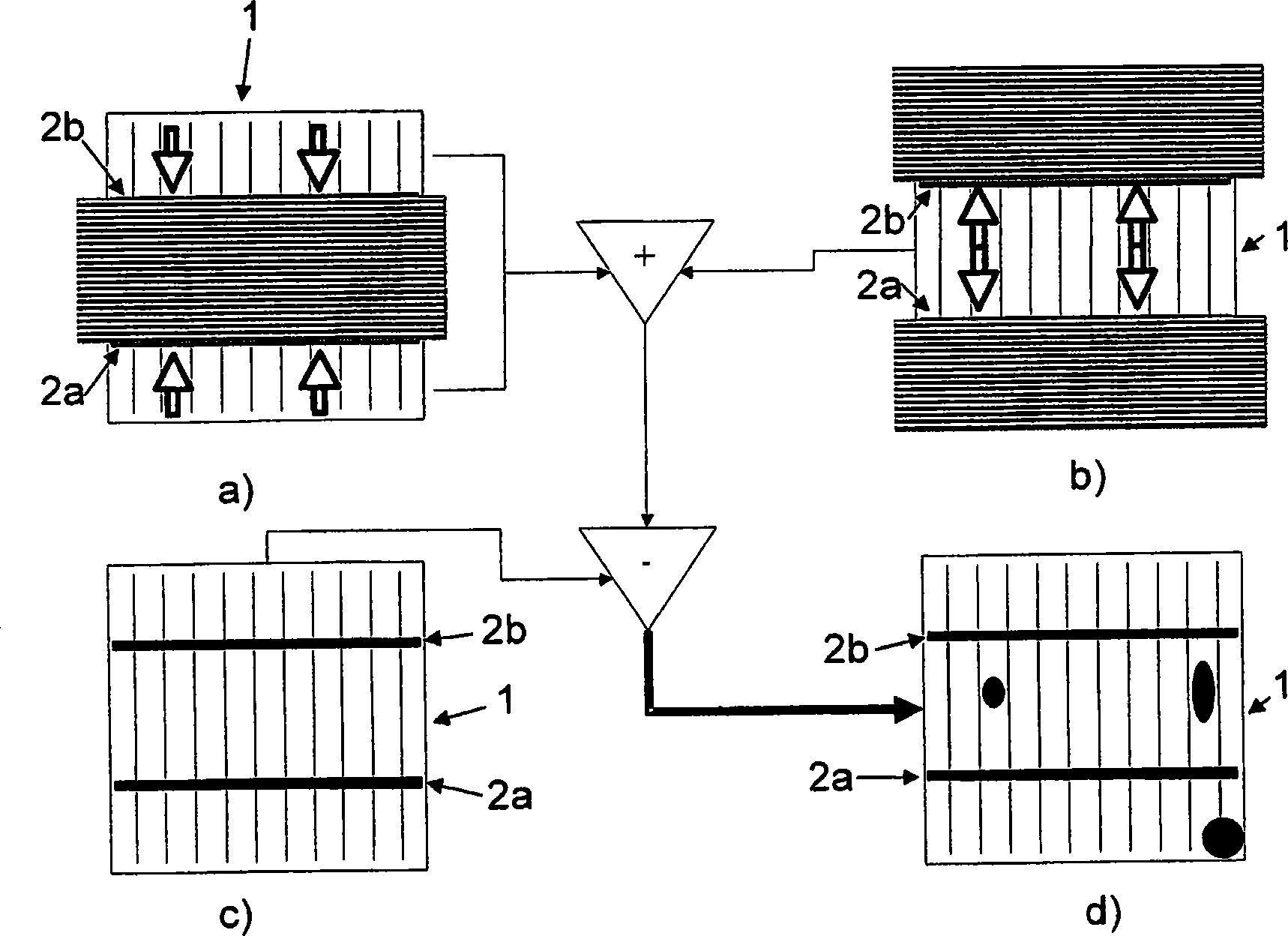
[0094] figure 1 The application of an embodiment of the measuring method for measuring a semiconductor component 1 according to the present invention is shown. The semiconductor component is designed as a solar cell with two metallization lines 2a and 2b extending parallel to each other. Lines are bus bars of metallized structure.

[0095] For the measurement, a conventional photoluminescence measuring device is used, which is extended with a correction unit with two optical filters.

[0096] During the measurement, the battery is not electrically connected. A total of three measurements are performed, and in each measurement, each camera of the measurement device performs photography with a measurement time of one second each. The difference between these three measurements is only in the shielding conditions for the excitation beam. The measuring surface is figure 1 The front side of the solar cell shown in a, b, c, d.

[0097] In the first measurement ( figure 1 a) In the fi...


PUM


Abstract

A measuring method and device for characterizing a semiconductor component (1) having a pn junction and a measuring surface, which has a contacting subarea, covered by a metallization. The method including: A. Planar application of electromagnetic excitation radiation onto the measuring area of the semiconductor component (1) for separating charge carrier pairs in the semiconductor component (1), and B. spatially resolved measurement of electromagnetic radiation originating from the semiconductor component (1) using a detection unit. In one step A, a predetermined excitation subarea of the measuring surface has a predetermined intensity of the excitation radiation and at least one sink subarea of the measuring surface has an intensity of the excitation radiation which is less than the intensity applied to the excitation subarea. The excitation and sink subareas are disposed on opposite sides of said contacting subarea and adjoin it and / or entirely or partially overlap it.

Description

Technical field [0001] The invention relates to a measuring method for characterizing semiconductor components according to the preamble of claim 1 and a measuring device for semiconductor components according to the preamble of claim 22. Background technique [0002] For determining the physical parameters in the semiconductor component, especially the loss mechanism / loss structure, a spatially resolved measurement method is advantageous because it is possible to assign a determined physical parameter or loss mechanism to the thus determined spatial partition of the semiconductor component, for example The spatial non-uniformity can be easily identified and analyzed in the manufacturing process of semiconductor components. [0003] These methods are used in particular in the characterization of semiconductor components in the form of semiconductor solar cells or precursors of such solar cells during the development process, that is, semiconductor elements having at least one PN ju...

Claims


Application Information

Patent Timeline
Patent Type & Authority Patents(China)
IPC IPC(8): G01R31/26
CPCG01R31/2605G01R31/2656H02S50/10Y02E10/50
Inventor J·卡斯滕森A·舒特H·福尔W·瓦尔塔M·凯斯曼
Owner FRAUNHOFER GESELLSCHAFT ZUR FOERDERUNG DER ANGEWANDTEN FORSCHUNG EV
Why Eureka
Try Eureka