Holographic recording method and holographic recording apparatus

a recording method and recording apparatus technology, applied in the field of holographic recording methods and holographic recording apparatuses, can solve the problems of reducing the fidelity of gradation display, limiting the device of polarization control type, and reducing the precision of gradation display

Inactive Publication Date: 2007-07-05
TDK CORPARATION
View PDF7 Cites 9 Cited by
  • Summary
  • Abstract
  • Description
  • Claims
  • Application Information

AI Technical Summary

Benefits of technology

[0027] (9) The holographic recording apparatus according to any one of (5) to (8), comprising a control unit for controlling the number of times of exposure within the exposure time t0 with respect to each of the pixels of the reflection type spatial light modulator, and wherein the control unit is configured to control the number of times of exposure within the exposure time t0 pixel by pixel so that a beam intensity distribution after the reflection by the reflection type spatial light modulator becomes generally uniform.
[0028] (10) The holographic recording apparatus according to (9), wherein the control unit is configured to control the number of times of exposure so that the object beam after the reflection becomes generally uniform in beam intensity, based on beam intensity distribution information on each area when the beam intensity distribution of the object beam immediately before incident on the reflection type spatial light modulator is divided into (N+1) levels of areas.

Problems solved by technology

Nevertheless, since image pickup devices have fixed noise independent of detection intensity, there is the problem that emphasizing darkened pixels can also emphasize the fixed noise with a drop in the SNR of the image.
With the method of dividing the contrast of intensity modulation, which is one of the methods of creating a gray-scale mentioned above, the spatial light modulator, or the means for intensity modulation, is limited to devices of polarization control type (such as a liquid crystal display).
A second problem of this method consists in that the gradation display requires fidelity of high precision.
This means the problem that devices containing analog elements such as liquid crystals cannot follow the high speed operation but be affected by afterimages and blurs.
There is a problem, however, since optical parts are expensive and can limit the degree of freedom of the optical system.

Method used


Image

  • Holographic recording method and holographic recording apparatus
  • Holographic recording method and holographic recording apparatus
  • Holographic recording method and holographic recording apparatus

Examples


first embodiment

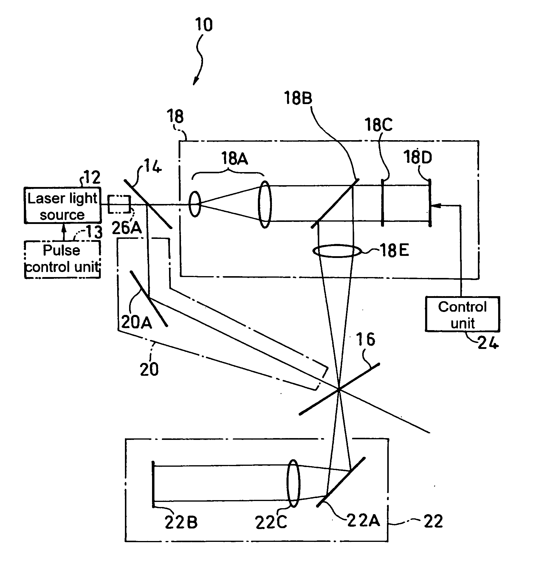
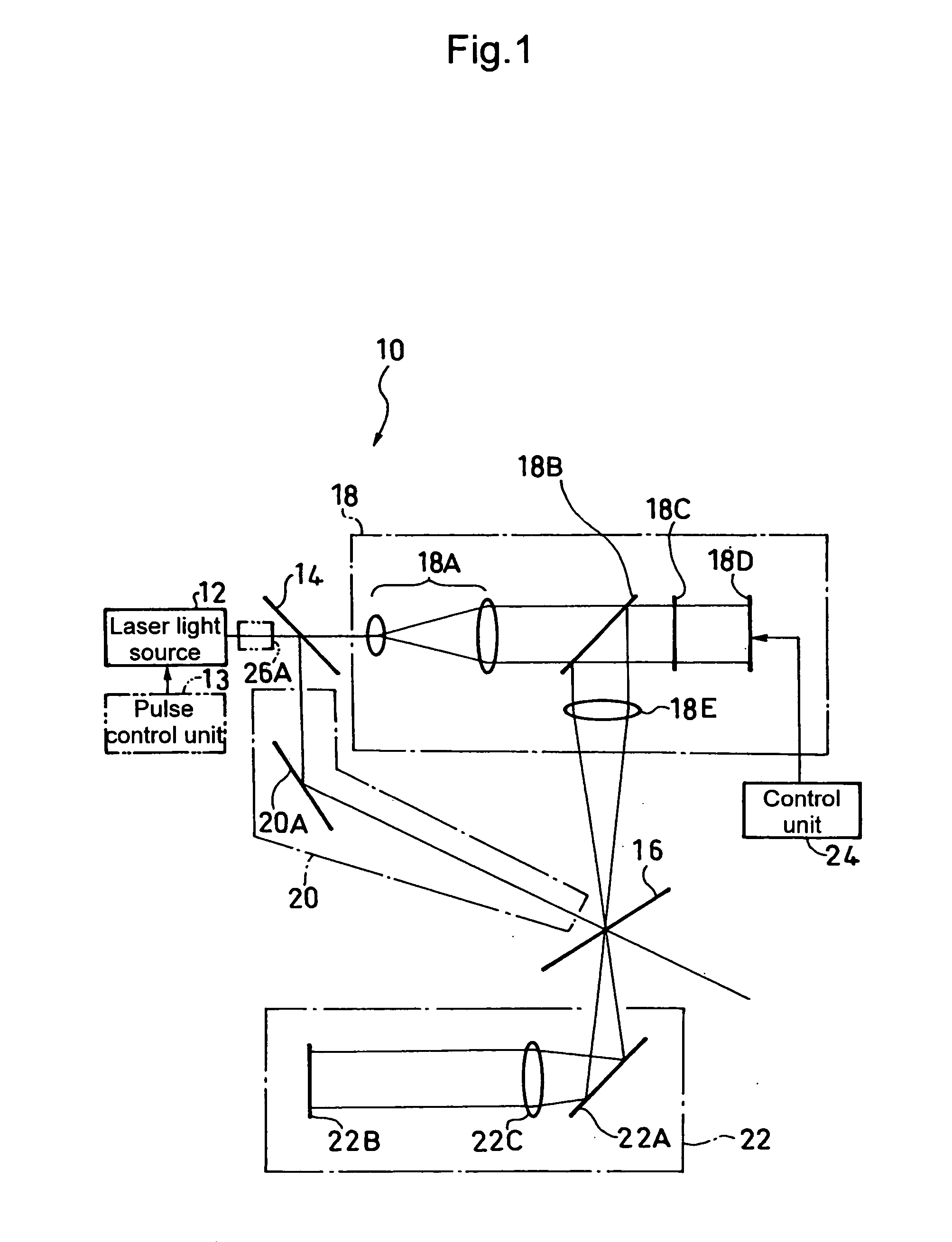
[0039] Hereinafter, a holographic recording apparatus 10 according to a first embodiment of the present invention will be described with reference to FIG. 1.

[0040] This holographic recording apparatus 10 is configured to include: a laser light source 12; a first polarizing beam splitter 14 for splitting a laser beam from this laser light source 12 into an object beam and a reference beam; an object optical system 18 for introducing the object beam, or the polarized light transmitted through the first polarizing beam splitter 14 such as p-polarized light, to a holographic recording medium 16; a reference optical system 20 for introducing the reference beam, or the polarized light reflected from the first polarizing beam splitter 14 such as s-polarized light, to the holographic recording medium 16; an imaging optical system 22 for reproducing a data page from diffracted light occurring from the holographic recording medium 16; and a control unit 24.

[0041] The object optical system 1...

second embodiment

[0064] Next, a second embodiment of the present invention will be described with reference to FIGS. 6 to 8.

[0065] This embodiment relates to a method of uniformizing an intensity distribution when the laser beam emitted from the laser light source has a Gaussian intensity distribution within its beam diameter, by using apodization through the division of the exposure time of a reflection type spatial light modulator without using expensive optical parts.

[0066] For example, assuming that the object beam on the optical path immediately before incident on the DMD 18D has such an intensity distribution within its beam diameter as shown in FIG. 9, the amount of light (light intensity) decreases like (P0 to P1)→(P1 to P2)→(P2 to P3)→(P3 to P4) in order of areas α, β, γ, and δ from the beam center to the radial outside of the beam diameter.

[0067] Corresponding to the areas α to δ having such respective light intensities, this second embodiment uniformizes the distribution of exposure in...


PUM

PropertyMeasurementUnit
areaaaaaaaaaaa
reflectionaaaaaaaaaa
exposure time t1aaaaaaaaaa

Abstract

A holographic recording apparatus 10 realizes multilevel gray-scale recording by: controlling a reflection type spatial light modulator (DMD 18D) via a control unit 24 so that an object beam in an object optical system 18 is reflected in an exposure direction so as to be incident on a holographic recording medium 16 or in a non-exposure direction so as not to be incident thereon selectively pixel by pixel in accordance with a data page to be recorded; and making (N+1) levels of gradation exposure with a single exposure time t1 given by dividing t0 by N, where to is an exposure time necessary for rendering a single pixel of the data page as an ON pixel, and N is an integer of not less than 2.

Description

TECHNICAL FIELD [0001] This invention relates to a holographic recording method and an apparatus for irradiating a holographic recording medium with an object beam and a reference beam so that a data page is recorded on a recording layer of the same in the form of interference fringes. BACKGROUND ART [0002] This kind of holographic recording method and apparatus includes ones in which digital information to be recorded is converted into a two-dimensional bitmap pattern and this pattern is given to an object beam through light intensity modulation so that it is recorded as a data page. [0003] Here, the bitmap pattern is typically rendered in light intensity modulation by using a spatial light modulator. Since this spatial light modulator is low in recording density as long as it intensity-modulates the object beam in two levels of ON and OFF pixel by pixel, attempts have conventionally been made to improve the recording density and data rate by means of a gray scale (so-called multil...

Claims


Application Information

Patent Timeline
Patent Type & Authority Applications(United States)
IPC IPC(8): G03H1/00G03H1/04G03H1/16G03H1/26G03H1/28G06K19/06G11B7/0065G11B7/125G11B7/1275G11B7/128
CPCG03H1/16G03H1/2645G03H1/28G03H2001/2655G03H2210/22G11B7/128G06K19/06037G06K2019/0629G11B7/0065G11B7/1275G03H2225/24
Inventor TSUKAGOSHI, TAKUYAYOSHINARI, JIROMIURA, HIDEAKIMIZUSHIMA, TETSURO
Owner TDK CORPARATION
Why Eureka
Try Eureka