
Microscopic bubble combined trapezoid spray tray and connection method of valve body and tray

A technology of micro-bubbles and mass transfer towers, applied in chemical instruments and methods, chemical/physical/physicochemical processes, fractionation, etc., can solve problems such as large liquid level drop, poor contact effect, liquid back-mixing, etc., and achieve height reduction , Reduce the spacing between the trays, and the effect of uniform gas distribution

Active Publication Date: 2012-08-08
TIANJIN UNIV
View PDF0 Cites 0 Cited by
  • Summary
  • Abstract
  • Description
  • Claims
  • Application Information

AI Technical Summary

Problems solved by technology

[0006] In order to overcome the shortcomings of traditional trays such as poor gas-liquid contact effect, large liquid level drop, easy liquid leakage, liquid back-mixing, etc., the present invention utilizes the particularity of the material structure that produces microbubbles to produce microbubble mass transfer trays

Method used


Image

  • Microscopic bubble combined trapezoid spray tray and connection method of valve body and tray
  • Microscopic bubble combined trapezoid spray tray and connection method of valve body and tray
  • Microscopic bubble combined trapezoid spray tray and connection method of valve body and tray

Examples


Embodiment 1

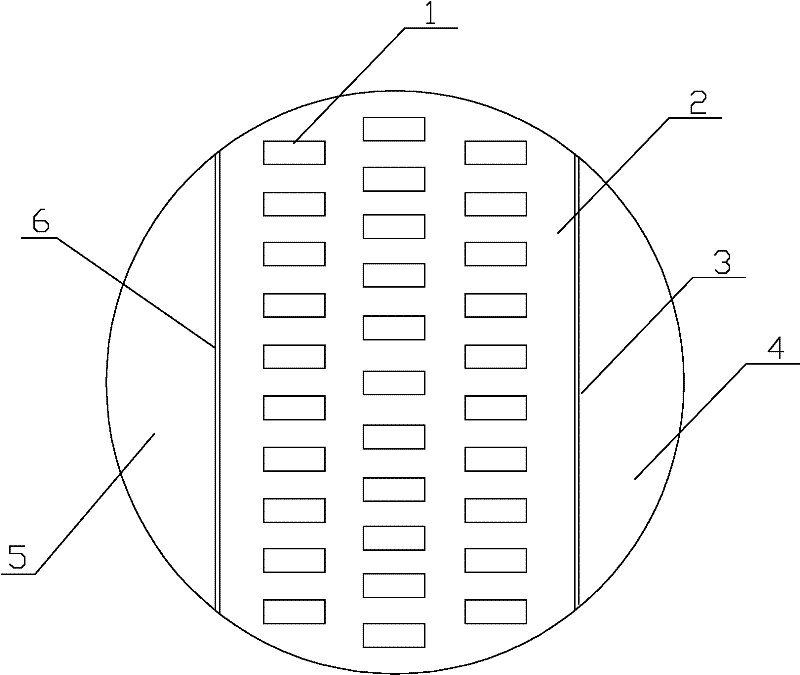
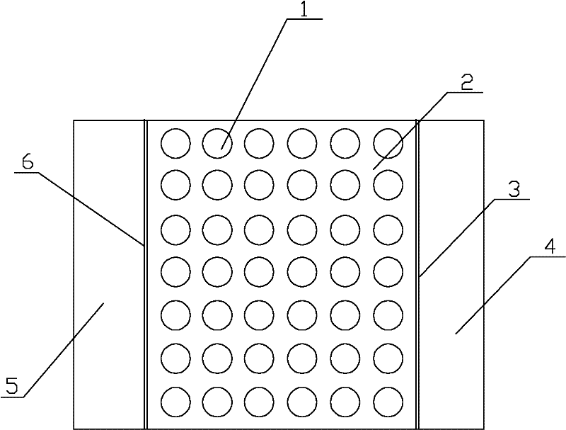
[0036] The microbubble mass transfer tray consists of a tray 2, a microbubble mass transfer valve body 7 arranged on the tray 2, a valve hole 1, and a liquid-receiving structure (downcomer 4, liquid-receiving tray 5, inlet weir 6 and Outlet weir 3) composition, wherein the tray structure such as figure 1 As shown, the relative position of the tray and the valve body is as follows Figure 4 As shown, the valve body structure is as Figure 9 shown. Among them, the valve body needs to be able to completely cover the valve hole, the cross-sectional area of ​​the microbubble mass transfer valve body is greater than the valve hole area, and the upper surface of the valve body is higher than the upper surface of the tray, and the height difference = the height of the valve body. The microbubble mass transfer valve body is made of ceramics with a pore volume fraction of 90% and a pore diameter of 0.1 mm. Its structure is a sponge-like porous structure. The valve body 7 is rectangula...

Embodiment 2

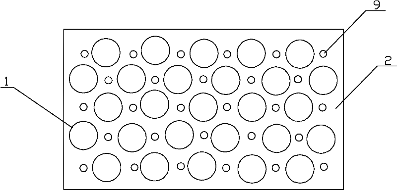
[0039] The microbubble mass transfer tray is composed of a tray 2, a microbubble mass transfer valve body 7 arranged on the tray 2, a valve hole 1, and a shower hole 9, wherein the tray structure figure 2 As shown, the relative position of the tray and the valve body is as follows Figure 5 As shown, the valve body structure is as Figure 10shown. Among them, the valve body needs to be able to completely cover the valve hole, the cross-sectional area of ​​the microbubble mass transfer valve body is greater than the valve hole area, and the upper surface of the valve body is higher than the upper surface of the tray, and the height difference is less than the height of the valve body. The microbubble mass transfer valve body with a pore volume fraction of 50-90% and a pore diameter of 0.1-5mm is made of silicon carbide, and its structure is an irregular porous structure. The valve body 7 is tightly connected to the tray by bonding / welding / inlaying, and the valve holes are st...

Embodiment 3

[0042] The microbubble mass transfer tray is composed of a tray 2, a microbubble mass transfer valve body 7 arranged on the tray 2, a valve hole 1, and a shower hole 9, wherein the tray structure figure 2 As shown, the relative position of the tray and the valve body is as follows Figure 6 As shown, the valve body structure is as Figure 10 shown. Wherein, the valve body needs to be able to completely cover the valve hole, the cross-sectional area of ​​the microbubble mass transfer valve body is greater than or equal to the valve hole area, and the height difference between the upper surface of the valve body and the upper surface of the tray = 0. A microbubble solid valve with a pore volume fraction of 50% and a pore diameter of 5 mm is made of resin. Its structure is a bundle-shaped porous structure. The valve body 7 is circular and is closely connected to the tray by bonding / welding / inlaying. , The valve holes are staggered.

[0043] When the tray is working, the liqui...


PUM


Abstract

The invention relates to a microscopic bubble combined trapezoid spray tray and a connection method of a valve body and a tray. The microscopic bubble combined trapezoid spray tray is mainly composed of a tray, a microscopic bubble mass transfer valve body and a valve port, wherein the microscopic bubble mass transfer valve body completely covers the valve port on the tray, and the cross section area of the microscopic bubble mass transfer valve body is more than or equal to the area of the valve pore; if the upper surface of the valve body is higher than the upper surface of the tray, the height difference between the upper surface of the valve body and the upper surface of the tray is less than or equal to the height of the valve body; if the upper surface of the valve body is lower than the upper surface of the tray, the height difference between the upper surface of the tray and the upper surface of the valve body is less than or equal to the thickness of the tray. Because the valve body and the tray are tightly mated, gaseous phase is upwards transferred by a pore on the valve body, the microscopic bubble structure is changed to provide even microscopic bubble gas distribution, increase contact surface between gas and a liquid layer and increase mass transfer efficiency. Because the microscopic bubbles are vertically upward, mutual injection does not occur so as to improve the situation that the traditional tray does not improve aperture ratio while preventing leakage; meanwhile, the operation elasticity can be simultaneously improved, and the tray production capability is improved.

Description

technical field [0001] The invention relates to an important equipment for gas-liquid contact for mass transfer and heat transfer in the fields of oil refining, petrochemical, chemical industry and other fields, such as trays, rectification and absorption. Background technique [0002] The plate tower is a plate-by-plate contact gas-liquid mass transfer equipment. There are several layers of horizontal trays placed at a certain distance in the tower body. According to the different types of trays, the trays are opened with holes of different shapes and sizes, or installed with floating or fixed valves. Each layer of trays is close to the tower wall. There is a downcomer. During operation, the liquid flows from the upper tray through the downcomer to the lower tray by gravity, and flows through the tray horizontally. The outlet weir on the tray will maintain a certain thickness of the flowing liquid layer on the plate; the gas flows from the bottom of the tower. Pushed by t...

Claims


Application Information

Patent Timeline
Patent Type & Authority Patents(China)
IPC IPC(8): B01D3/18B01J19/32
Inventor 李鑫钢李洪姜斌张劲松杨振明
Owner TIANJIN UNIV
Learn More