Separated-combined type oil tank

A combined type and fuel tank technology, which is applied in the layout combined with the internal combustion engine fuel supply, mechanical equipment, transportation and packaging, etc., can solve the problems of no patent declaration, etc., and achieve the effect of solving installation and layout problems, convenient maintenance, and beautiful appearance

Inactive Publication Date: 2011-02-16
FAW GROUP
View PDF0 Cites 5 Cited by
  • Summary
  • Abstract
  • Description
  • Claims
  • Application Information

AI Technical Summary

Problems solved by technology

[0008] Searching patents found that there is no patent declaration of the same type

Method used


Image

  • Separated-combined type oil tank
  • Separated-combined type oil tank
  • Separated-combined type oil tank

Examples


Embodiment 1

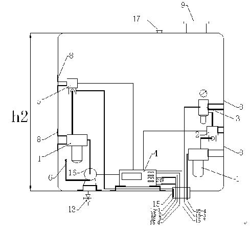
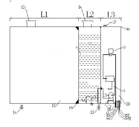
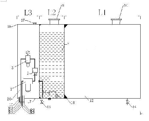
[0030] The selected material is SUS304 or SUS441 stainless steel plate, its thickness is 1.2mm, the volume capacity relationship L1 / L2=30 between fuel tank body 12 and reductant tank body 7; Holes, rolls, and welding are made into fuel tank (12), urea reducing agent box 7 and electrical control box 20 respectively. After the combined fuel tank is installed on the vehicle, the fuel tank 12 is arranged on the vehicle The position is the farthest from the engine, while the urea reducing agent box 7 and the electrical control box 20 are arranged on the vehicle at the shortest distance from the engine. The combined fuel tank is fixed on the vehicle frame with a bracket; The fuel tank cover 9 and the fuel tank cover 10 are facing the outside of the compartment; at the same time, fill the full-scale fuel and urea reducing agent, the consumption rate of the urea reducing agent is 1 / 20~1 / 30 of the fuel, and the amount of the two liquids can almost maintain Refill the mileage at the sam...

Embodiment 2

[0032] The selected material is SUS304 or SUS441 stainless steel plate, its thickness is 1.4mm, the volume capacity relation L1 / L2=20 of fuel tank body 12 and reductant tank body 7; Holes, rolled plates, and welding are made into fuel tank 12, urea reducing agent box 7 and electrical control box 20 respectively. After the combined fuel tank is installed on the vehicle, the fuel tank 12 is arranged on the vehicle. It is the farthest from the engine, and the position on the vehicle where the urea reducing agent box 7 and the electrical control box 20 are arranged is the closest to the engine. The combined fuel tank is fixed on the vehicle frame with a bracket; the urea reducing agent box The cover 9 and the fuel tank cover 10 are facing the outside of the compartment; at the same time, the full scale fuel and urea reducing agent are filled, the consumption rate of the urea reducing agent is 1 / 20~1 / 25 of the fuel, and the amount of the two liquids can be maintained almost at the s...

Embodiment 3

[0034] The selected material is SUS304 or SUS441 stainless steel plate, its thickness is 1.5mm, the volume capacity relation L1 / L2=10 of fuel tank body 12 and reductant tank body 7; Holes, rolled plates, and welding are made into fuel tank 12, urea reducing agent box 7 and electrical control box 20 respectively. After the combined fuel tank is installed on the vehicle, the fuel tank 12 is arranged on the vehicle. It is the farthest from the engine, and the position on the vehicle where the urea reducing agent box 7 and the electrical control box 20 are arranged is the closest to the engine. The combined fuel tank is fixed on the vehicle frame with a bracket; the urea reducing agent box The cover 9 and the fuel tank cover 10 face the outside of the compartment; at the same time, fill the full-scale fuel and urea reducing agent. The fuel mileage of the tank is suitable for areas where there are few urea reducing agent filling stations, reducing troubles, and meeting the needs of...


PUM


Abstract

The invention relates to a separated-combined type oil tank, which is characterized in that one side of the oil tank is provided with a fuel oil tank body, the middle of the oil tank is wielded with a urea reducing agent tank body, while the other side thereof is fixed with an electrically control tank; the volume capacity relation of the fuel oil tank body and the urea reducing agent tank body is as follows: L1/L2=10-30, and the capacity L3 of the electrically control tank is 120-150mm; and one side of the electrically control tank is provided with a buckle of a seaming end cover. In the invention, on the basis of the traditional automobile oil tank, the urea reducing agent tank and a dosage control tank of a urea reducing agent are combined, thereby enabling one tank body to have three functions, thus the method of the invention realizes the compact design which is beneficial for the beautiful design of vehicles, reduces the mounting of connecting parts, simplifies the vehicle allocation, reduces the weight, meets the using requirement of the SRC standard higher than nation 4, and reduces the cost of the system.

Description

technical field [0001] The invention relates to a separated and combined fuel tank, which is applied to the post-treatment industry of automobile exhaust. Background technique [0002] In the next few years, automobile manufacturers around the world, especially the United States and Europe, will enforce some stricter standards on vehicle nitrogen oxides NOx and particulate PM emissions, such as Euro V and Euro VI emission standards. [0003] Under the pressure of emission regulations, on the one hand, foreign heavy-duty diesel engines for vehicles are constantly upgrading and improving their technology; , DPF (Diesel Particulate Filter) particle trap, DOC (Diesel Oxidation Catalyst) oxidation catalyst, etc. [0004] The essence of SCR technology is to use urea to decompose NH at high temperature 3 , NH as reducing agent 3 and NO in engine exhaust x The reaction is carried out under the combined action of catalyst and temperature, and under ideal conditions, non-toxic N ...

Claims


Application Information

Patent Timeline
Patent Type & Authority Applications(China)
IPC IPC(8): B60K15/073F01N3/20
CPCY02T10/24Y02A50/20Y02T10/12
Inventor 张克金崔龙王丹张苡铭李凤伟魏晓川杨彬刘国军
Owner FAW GROUP
Why Eureka
Try Eureka