Hybrid magnetic bearing of rotor inside vertical coil and assembled structure thereof

A hybrid magnetic bearing and vertical coil technology, applied in the directions of magnetic bearings, bearings, shafts and bearings, can solve the problems of difficulty, complex structure, increase the power consumption of the drive motor, etc., and achieve the design structure simplification, eddy current loss and blocking torque. The effect of reducing the magnetic circuit coupling effect is small

Inactive Publication Date: 2014-01-22
NAT UNIV OF DEFENSE TECH
View PDF5 Cites 0 Cited by
  • Summary
  • Abstract
  • Description
  • Claims
  • Application Information

AI Technical Summary

Problems solved by technology

[0005] Therefore, for high-speed flywheel rotors, the current hybrid magnetic bearings still have obvious technical disadvantages: on the one hand, the eddy current in the rotor core will produce a significant retarding torque, which will be significant in aerospace applications such as magnetic levitation flywheels for attitude control. Increase the power consumption of the drive motor and affect the stability and accuracy of satellite attitude control; on the other hand, when the high-speed rotor is enclosed in a high-vacuum shell in order to reduce windage loss, excessive eddy current loss will also increase the heat dissipation of the rotor design difficulties
In addition, the current hybrid magnetic bearing coil core and the working magnetic pole adopt an integrated structure, which has disadvantages such as complex structure and inability to fully utilize the circumferential area of ​​the magnetic pole.

Method used


Image

  • Hybrid magnetic bearing of rotor inside vertical coil and assembled structure thereof
  • Hybrid magnetic bearing of rotor inside vertical coil and assembled structure thereof
  • Hybrid magnetic bearing of rotor inside vertical coil and assembled structure thereof

Examples


Embodiment 1

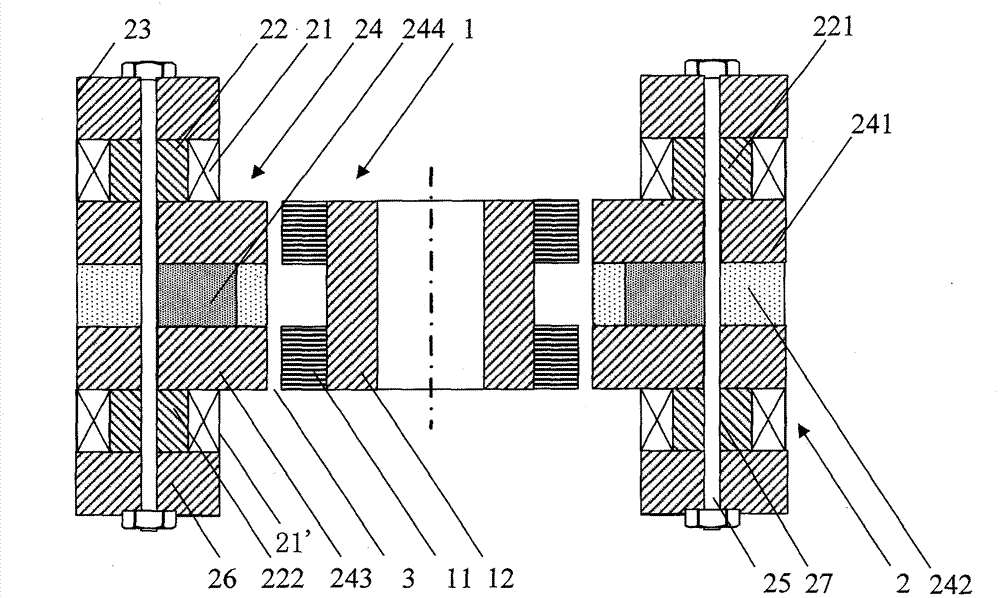
[0066] see Figure 1-Figure 3 , This embodiment of the present invention is made up of rotor 1 and stator 2 two major parts such as above-mentioned scheme. The rotor 1 is installed inside the stator 2 to form an inner rotor. The rotor 1 is composed of a rotor core 11 and an inner magnetically permeable ring 12 , wherein the rotor core 11 is coaxially sleeved on the outside of the inner magnetically permeable ring 12 . The rotor core 11 of the rotor 1 is made of a thin-plate soft magnetic material with good magnetic permeability, such as electrical silicon steel plate, which is stamped and stacked; The cover plate 23, the stator plate 24, four connecting rods 25 and the lower magnetically conductive cover plate 26 are composed of the upper magnetically conductive cover plate 23, the coil core 22, the stator plate 24, and the lower magnetically conductive cover plate 26 in sequence. connected into a whole. The stator disk 24 is composed of an upper magnetically conductive pol...

Embodiment 2

[0070] The hybrid magnetic bearing of the present invention can also be constructed in different ways in its combined structure. For example, if Figure 5 As shown, adopt two sets along the axial direction such as figure 1 The basic structure shown can constitute a magnetic bearing with radial four-axis active control and axial passive stability, that is, the present invention can be designed as a combination of multiple basic structures to meet different requirements. For this combined magnetic bearing, a non-magnetic spacer ring 8 can be set between the upper and lower magnetic bearing stators, and a non-magnetic spacer ring 9 can be set between the upper and lower magnetic bearing rotors 1 . Both the spacer ring 8 and the spacer ring 9 are made of non-magnetic aluminum alloy, copper or non-magnetic stainless steel. In this embodiment, as far as the single product of the present invention is concerned, except that the magnetization directions of the permanent magnets in th...


PUM


Abstract

The invention relates to a hybrid magnetic bearing of a rotor inside a vertical coil and an assembled structure thereof. The hybrid magnetic bearing comprises a rotor and a stator, wherein the rotor comprises an inner magnetic conductive ring and a rotor core, wherein the rotor core is coaxially sleeved at the outer side of the inner magnetic conductive ring; the stator comprises a stator disc, a plurality of coil iron cores and a plurality of electromagnetic coils, wherein the stator disc includes an upper magnetic conductive pole plate, a lower magnetic conductive pole plate, a magnetic pillar installation disc and a permanent magnet; the plurality of coil iron cores are respectively symmetrically arranged at the upper side and the lower side of the stator disc and uniformly distributed along the circumferential direction of the stator disc, and every two coil cores which are symmetrically arranged at the top and the bottom respectively correspond to the position of one magnetic pole; the plurality of electromagnetic coils are respectively vertically sleeved on the coil iron cores; the rotor is arranged in the stator; and the magnetic conductive pole plates are respectively uniformly divided into four-magnetic pole structures in radial shapes along the circumferential direction, and the magnetic poles are connected into an integral ring on an inner edge. The magnetic poles of the hybrid magnetic bearing are connected into the integral ring so as to form radial uniform magnetic poles, therefore the eddy current loss of the rotor during operation is greatly reduced.

Description

technical field [0001] The invention relates to a non-contact magnetic suspension bearing, in particular to a hybrid magnetic bearing that can be used as a non-contact support for rotating components, and is especially suitable for non-contact support of satellite attitude control magnetic suspension flywheels and energy storage flywheels. Background technique [0002] Magnetic suspension bearings are divided into pure electromagnetic bearings and hybrid magnetic suspension bearings with permanent magnetic bias and electromagnetic control. The former must set a bias current in the electromagnetic coil to provide a working point for the magnetic bearing, so the control current is large and the power consumption is large; while In the hybrid magnetic suspension bearing with permanent magnet bias and electromagnetic control, the permanent magnet provides the main magnetic flux of the magnetic circuit and the magnetic field of the bias operating point, and bears the main bearing ...

Claims


Application Information

Patent Timeline
Patent Type & Authority Patents(China)
IPC IPC(8): F16C32/04
CPCF16C32/044
Inventor 肖凯张育林刘昆单小强张立
Owner NAT UNIV OF DEFENSE TECH
Why Eureka
Try Eureka