Self-sealed zero leakage hydrophobic molded surface mechanical sealing end face structure

A mechanical seal and hydrophobic technology, applied in the direction of mechanical equipment, engine seals, engine components, etc., can solve the problems of increased end face opening force, increased leakage rate, increased frictional heat, etc., to improve sealing performance and wear resistance damage performance, improve opening characteristics and reliability, and prevent dry wear

Active Publication Date: 2011-02-16
SICHUAN ZIGONG IND PUMP
View PDF7 Cites 23 Cited by
  • Summary
  • Abstract
  • Description
  • Claims
  • Application Information

AI Technical Summary

Problems solved by technology

When the non-contact mechanical seal with grooves such as spiral grooves operates normally, the end face groove generates fluid dynamic pressure, which increases the opening force of the end face, and the increase of fluid film thickness leads to an increase in leakage rate; at the same time, the hardness in the medium increases. The grinding debris generated by high-quality abrasives and the end face during start-stop is also easy to accumulate at the root of the groove and cause wear to the end face, resulting in seal failure
When the contact mechanical seal is started, the lack of fluid lubrication between the end faces will cause frictional heat to rise and be accompanied by wear, deformation or even thermal cracking, so the seal life is short

Method used


Image

  • Self-sealed zero leakage hydrophobic molded surface mechanical sealing end face structure
  • Self-sealed zero leakage hydrophobic molded surface mechanical sealing end face structure
  • Self-sealed zero leakage hydrophobic molded surface mechanical sealing end face structure

Examples


Embodiment 1

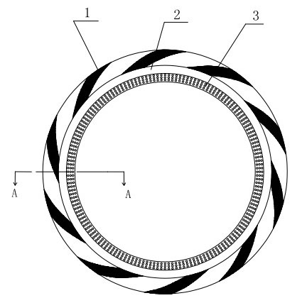
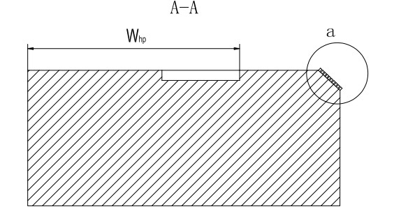
[0027] refer to Figure 1-3 , a self-sealing zero-leakage hydrophobic profile mechanical seal end face structure, including a dynamic ring and a static ring of the mechanical seal, one side of the end faces of the dynamic ring and the static ring is the high pressure side, that is, the upstream, the dynamic ring and the static ring The other side of the end face is the low-pressure side, that is, the downstream side. At least one sealing end face of the moving ring or the static ring is composed of a micro-groove dynamic pressure ring 1, a sealing dam 2 and a hydrophobic Profile 3 is a composite profile composed of the three.

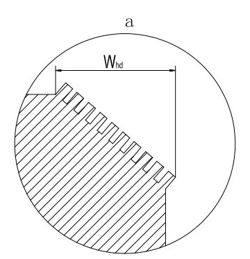
[0028] The hydrophobic profile 3 is a regular textured tapered surface composed of micro-nano scale columns.

[0029] The sealing dam 2 is a smooth plane without micro-grooves, micro-pillars or pits.

[0030] The micro-groove dynamic pressure ring belt 1 is composed of micro-grooves radially uniformly distributed on the sealing end surface.

[0031] ...

Embodiment 2

[0034] refer to Figure 4-6 The difference between this embodiment and the first embodiment is that the hydrophobic profile 3 is a regularly textured plane or a regularly textured conical surface composed of micro-nano scale pits. The diameter of micro-nano-scale pits is 0.05-5 μm, the pitch of micro-nano-scale pits is 0.1-5 μm, and the depth of micro-nano-scale pits is 0.05-1 μm; the setting of dimple hydrophobic surface 3 is beneficial to prevent leakage The flow of the medium, and can accommodate the end face wear debris, so it has the characteristics of low leakage and wear resistance. The rest of the structures and functions are the same as those in Embodiment 1.

Embodiment 3

[0036] refer to Figure 7 , The difference between this embodiment and Embodiment 1 or Embodiment 2 is that a plurality of hydrophobic profiles 3 are provided on the sealing end surface. When multiple micropillars or micro-concave hydrophobic profiles are installed, only one annular seal dam 2 is required on the entire sealing end surface, and the width of the seal dam 2 is 0.5-1.5mm. Only when the medium pressure exceeds 1.5MPa, it is considered to install The width of the two above-mentioned sealing dams 2 or sealing dams 2 is 1.5-5 mm. This structure is suitable for occasions where the content of solid abrasive in the medium is high and the requirements for leakage rate control are high. The rest of the structures and functions are the same as those in the first or second embodiment.


PUM


Abstract

The invention discloses a self-sealed zero leakage hydrophobic molded surface mechanical sealing end face structure, which comprises a dynamic ring and a static ring which are mechanically sealed, wherein at least one sealed end face of the dynamic ring or the static ring is a composite molded surface consisting of a microgroove dynamic pressure ring belt, a sealed dam and a hydrophobic molded surface distributed in turn from high to low direction. The structure has the advantages that: the self-sealing property of the narrow hydrophobic molded surface can obviously reduce the leakage and even reaches zero leakage; by adopting one or more hydrophobic molded surfaces, the abrasion of the end faces can be reduced or avoided, and the integral sealing property and the abrasion resistance of mechanical seal can be greatly improved; and by adopting the combination mode of the microgroove dynamic pressure ring belt and the hydrophobic molded surface, a lubricating medium can be stored in the end faces to prevent dry grinding of the end faces when the machine is started and improve the opening property and the reliability of mechanical seal.

Description

technical field [0001] The invention belongs to the technical field of mechanical end face sealing, in particular to a shaft end sealing device suitable for rotating shafts of various compressors, pumps, kettles, etc. Hydrophobic surface mechanical seal end face structure. Background technique [0002] The shaft seal of fluid machinery often uses mechanical seals, packing seals, oil seals, labyrinth seals, etc. When the non-contact mechanical seal with grooves such as spiral grooves operates normally, the end face groove generates fluid dynamic pressure, which increases the opening force of the end face, and the increase in fluid film thickness leads to an increase in leakage rate; at the same time, the hardness in the medium increases. The grinding debris produced by high-quality abrasives and the end face during start-stop is also easy to accumulate at the root of the groove and cause wear to the end face, resulting in seal failure. When the contact mechanical seal is st...

Claims


Application Information

Patent Timeline
Patent Type & Authority Applications(China)
IPC IPC(8): F16J15/16
CPCF16J15/3412F16J15/3404F16J15/3424
Inventor 彭旭东刘鑫李纪云孟祥铠盛颂恩
Owner SICHUAN ZIGONG IND PUMP
Why Eureka
Try Eureka