High-efficiency dielectric lens antenna based on novel open-celled structure

A technology of dielectric lens antenna and Lumberg lens antenna, which is applied to antennas, antenna supports/installation devices, electrical components, etc., can solve the problems of complicated column holes, high cost, and difficult combination of each layer, and can offset the antenna gain. reduce the cost of processing, and facilitate the effect of installation and fixation

Inactive Publication Date: 2011-02-16
UNIV OF ELECTRONICS SCI & TECH OF CHINA
View PDF6 Cites 30 Cited by
  • Summary
  • Abstract
  • Description
  • Claims
  • Application Information

AI Technical Summary

Problems solved by technology

However, this technical requirement is very strict on the control of foaming agent, expansion temperature and selection of raw materials, and it also has very strict requirements on the chemical and physical characteristics of the material. Production is relatively difficult
Generally speaking, the baking time and temperature control of the Lumber lens antenna based on the foaming process are different for the processing of lens spherical shells with different dielectric constants, sizes, and thicknesses. It is difficult to find a more general foaming rule, so that It is more difficult and costly to obtain actual engineering mass production
[0006] There are many ways to realize the Lunberg lens antenna through the aperture structure. Compared with other aperture structures, D.M.Harrison et al. published a paper titled "A Hemispherical lens antenna for multi-satellite reception" on Antennas and Propagation Society International Symposium, 1992. In ", multiple layers of polystyrene material with hemispherical holes are used, and then each layer of hemispherical holes is aligned and pasted to form a complete spherical hole, and then multiple sheets of polystyrene with multiple complete spherical holes are used to make a hemisphere Body, thus made a dielectric lens antenna with an equivalent dielectric constant of 1.52, its gain performance is better under the measurement of a specific focal length, but due to the multi-layer hemispherical hole, the spherical hole is difficult to process in practice, and the size is relatively small Small lenses can still be made barely, and the complexity and cost will undoubtedly be greatly increased in the manufacture of larger electrical si

Method used


Image

  • High-efficiency dielectric lens antenna based on novel open-celled structure
  • High-efficiency dielectric lens antenna based on novel open-celled structure
  • High-efficiency dielectric lens antenna based on novel open-celled structure

Examples


Embodiment Construction

[0023] specific implementation plan

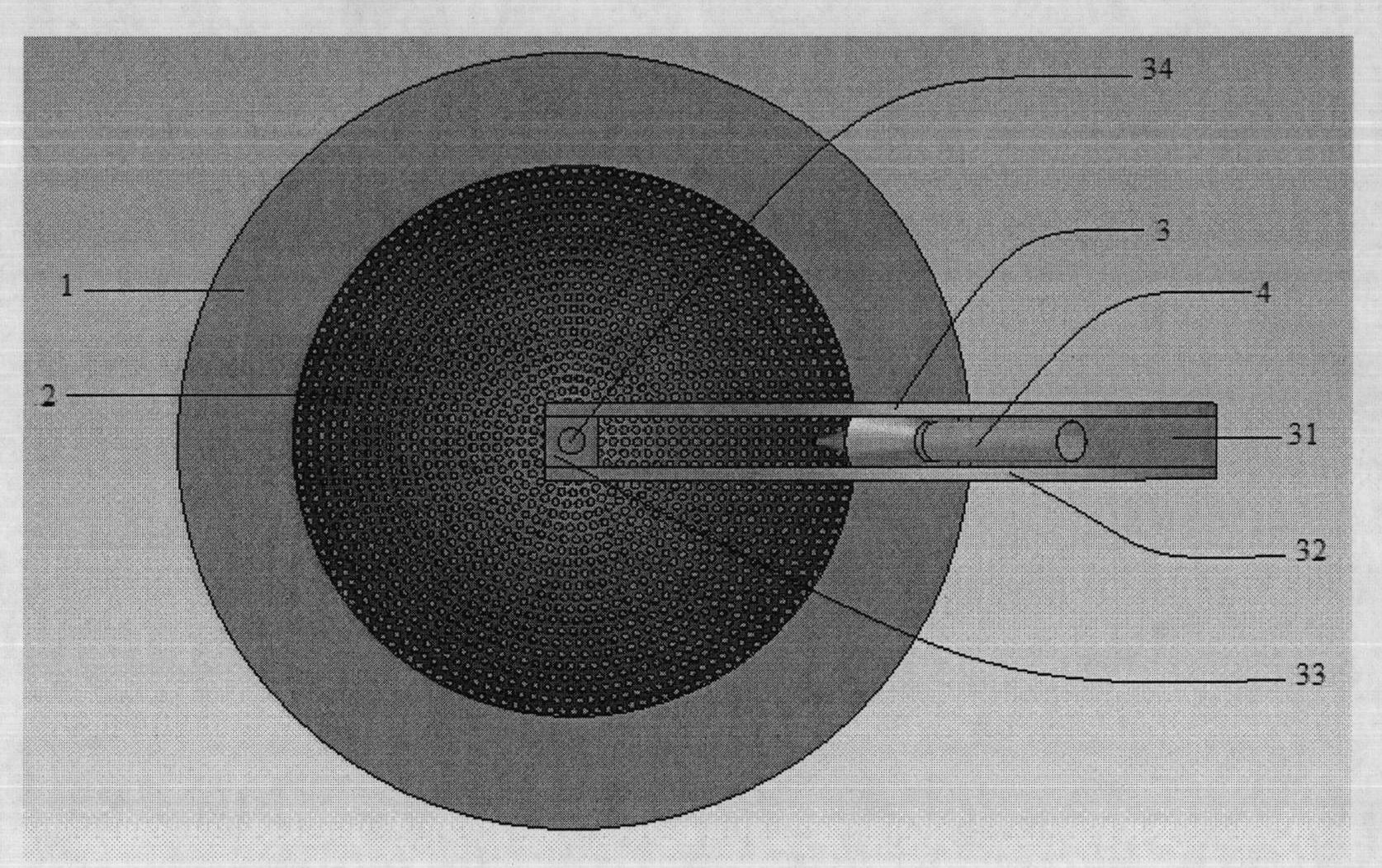
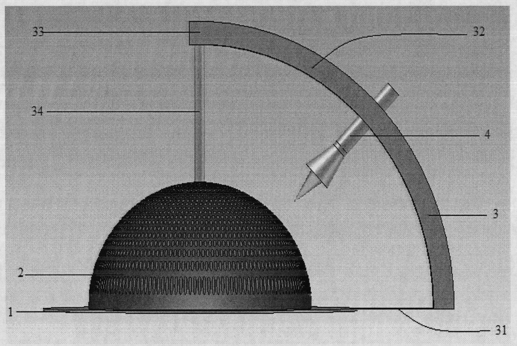
[0024] figure 1 with figure 2 Exemplarily described is a dielectric lens antenna design device with a high efficiency equivalent dielectric constant. According to the illustration, the device mainly includes a metal reflector, a bracket rail, a dielectric lens, and a high-efficiency feed. The metal reflector 1 is made of super duralumin plate, and of course it can also be made of other metal materials such as stainless steel. The metal reflector mainly plays the role of reflecting internal electromagnetic waves and shielding external interference.

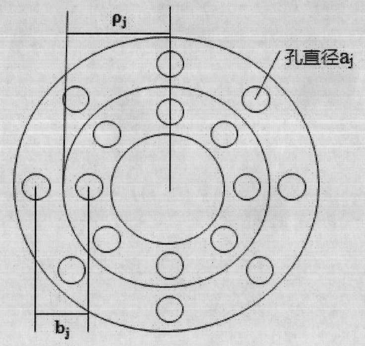
[0025] The dielectric lens part 2 is fixed on the metal reflector 1 by means of the dielectric bracket 3 . In particular, in the present invention, the hole structure of the dielectric lens is designed as a cylindrical hole structure. Specifically, cylindrical holes with a certain regularity and uniform distribution are drilled on a polytetrafluoroethylene with a large dielectric constant a...


PUM


Abstract

The invention discloses a dielectric lens antenna applied to wireless satellite communication in a luneberg lens antenna system. The basic structure of the dielectric lens antenna comprises a metallic reflecting plate part, a feed-source bracket part, a dielectric lens part and a feed-source part. The metallic reflecting plate part mainly performs shielding and reflecting actions. The dielectric lens part is formed by drilling a cylindrical hole in polytetrafluoroethylene and fixed on the metallic reflecting plate. The feed-source bracket is fixed between the metallic reflecting plate and the dielectric lens, the feed source is fixed on the feed-source bracket, and the incident and emergent foci and the beam angle of the feed source are determined through the slide and the extension of the feed source on the feed-source bracket. Based on the basic structure of the invention, the position, the size and the shape of an air hole are reasonably changed so as to form other concrete embodiments of the invention.

Description

technical field [0001] The invention belongs to the technical field of antenna engineering, and relates to a dielectric lens antenna, in particular to a dielectric lens with a required dielectric constant used in a Lunberg lens antenna system for satellite communications. Background technique [0002] Today, with the rapid development of satellite wireless communication, as the main carrier of signal transmission and reception, antenna plays a decisive role in the network construction of wireless communication system. Domestically, the development of live broadcast satellites is paid more and more attention to, and the demand for one-line multi-satellite receiving technology is increasing day by day. Based on this premise and combined with some research work of its own, the present invention designs an efficient one-line multi-satellite receiving antenna. [0003] Traditional satellite receiving antennas are parabolic antennas and Cassegrain antennas, which have the advantag...

Claims


Application Information

Patent Timeline
IPC IPC(8): H01Q1/12H01Q15/08H01Q19/06H01Q19/10
Inventor 杨仕文刘志佳黄明聂在平
Owner UNIV OF ELECTRONICS SCI & TECH OF CHINA
Why Eureka
Try Eureka