
Connection pin and electrical connection

A technology of connecting heads and connecting pins, which is applied to the connection of conductive adhesives, the shape of heating elements, and the device that coats the surface with liquid. Effect

Active Publication Date: 2013-07-17
GUENTHER HEISSKANALTECHNIK GMBH
View PDF6 Cites 0 Cited by
  • Summary
  • Abstract
  • Description
  • Claims
  • Application Information

AI Technical Summary

Problems solved by technology

Therefore, a connection with optimum shear strength cannot be achieved by means of the techniques described above
Furthermore, depending on the type of contact paste, sticking problems can arise at higher temperatures, which is especially disadvantageous in hot-runner nozzles, especially when the contact is completely or partially loosened

Method used


Image

  • Connection pin and electrical connection
  • Connection pin and electrical connection
  • Connection pin and electrical connection

Examples


Embodiment Construction

[0031] The same reference numbers refer to the same or similar components below.

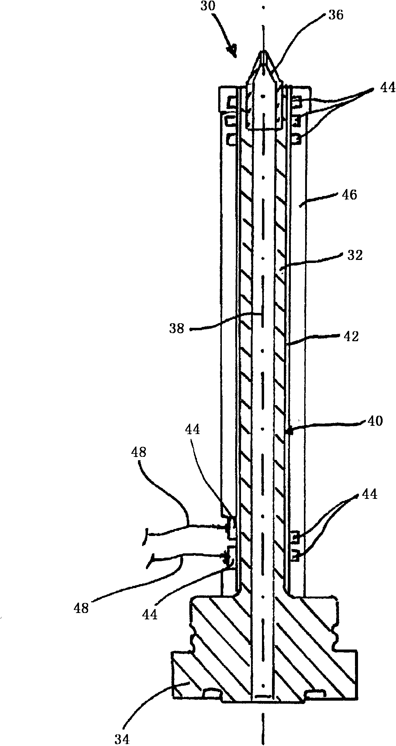
[0032] figure 2 Injection molding nozzle 30 shown in , as a component of an injection molding plant for thermoplastics processing, has a housing (also not shown) for attachment to a (not shown) distributor, overall cylindrical material A tube 32 can be inserted into the housing.

[0033] A seat 34 formed on the end side of the material tube closes flush with the housing and rests sealingly against the distributor. On the end side, a nozzle tip 36 is inserted, preferably screwed, into the axially longitudinally extending material tube 32 , which continues the flow channel 38 formed in the material tube 32 to the (likewise not visible) on the plane of the mold cavity (not shown). With the same operating principle, the nozzle tip 36 can also be formed in one piece with the material tube 32 .

[0034] A ceramic dielectric layer 42 is applied on the periphery of the wall 40 of the material tube ...


PUM


Abstract

A hookup stem (48; 70) to implement an electric hookup (50; 60) of an electric heater of an injection molding nozzle (30), the hookup stem (48; 70) being designed in a manner that it can be affixed by means of at least one electrically conducting adhesion layer (52; 62; 64; 66) and / or by a contact paste (52) to the heater, the hookup stem comprising a shank element (54; 72), and a connecting segment (56; 74) coming into contact with the minimum of one adhesion layer (52; 62; 64; 66) or the contact paste (52).

Description

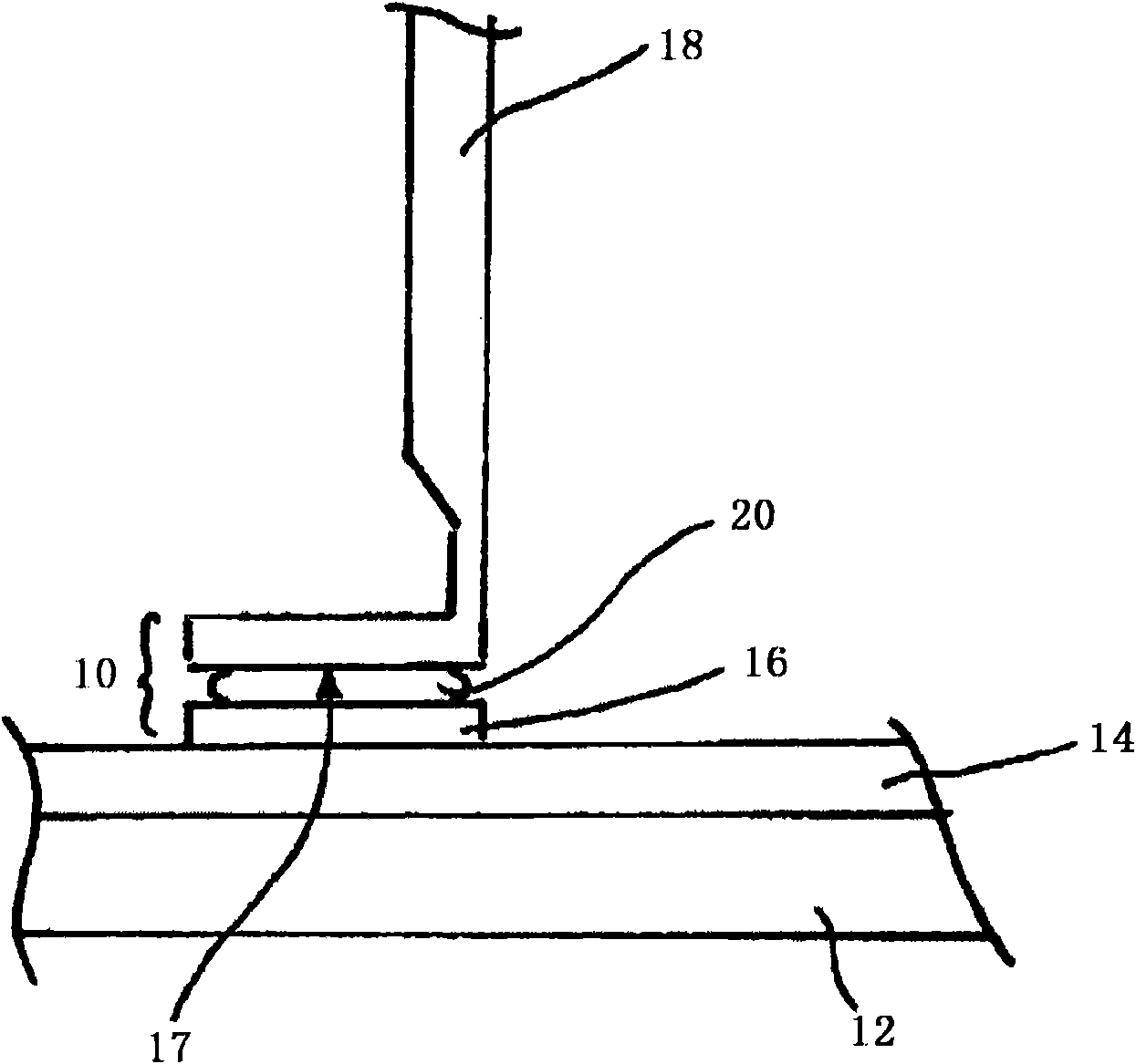
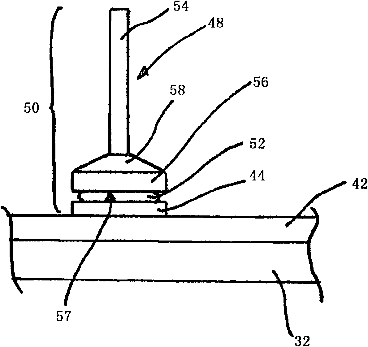
technical field [0001] The invention relates to a connecting pin for an electrical connection of an electrical heating device for producing an injection molding nozzle according to the preamble of claim 1 and to an electrical connection according to claim 6 . Background technique [0002] Electrical connections for electrical heaters of injection molding nozzles are known in various designs from the prior art. One possibility for producing such an electrical connection is, for example, to fasten the connecting lines connected to the power supply or the regulating device to the heating conductor strip of the electric heating device by means of contact paste. The contact paste is electrically conductive, whereby an electrical connection of the heating device is produced. [0003] figure 1 A schematic diagram of a known electrical connector 10 is shown. Reference numeral 12 designates an electrically conductive substrate, which can be, for example, a material tube of a hot-r...

Claims


Application Information

Patent Timeline
Patent Type & Authority Patents(China)
IPC IPC(8): H01R4/04B29C45/27H05B3/42B05C17/005
CPCH05B3/42B29C45/2737B29C2045/2745B29C2045/2751H01R4/04B05C17/00546
Inventor 赫伯特·君特西埃格丽德·佐默克里斯特尔·克雷奇马尔乌韦·帕尔奇
Owner GUENTHER HEISSKANALTECHNIK GMBH
Learn More