Self-maintained friction stir welding method with reversely rotating upper and lower shaft shoulders

A friction stir and welding method technology, applied in welding equipment, non-electric welding equipment, metal processing equipment, etc., can solve the problems of asymmetric residual stress distribution in the joint structure of the temperature field, reducing the bearing capacity of the welded structure, and asymmetric joint performance. Achieve the effect of improving mechanical properties, reducing softening degree and reducing asymmetry

Inactive Publication Date: 2011-02-23
HARBIN INST OF TECH
View PDF4 Cites 15 Cited by
  • Summary
  • Abstract
  • Description
  • Claims
  • Application Information

AI Technical Summary

Problems solved by technology

[0003] The purpose of the present invention is to solve the problem of large welding heat input caused by the rotation of the upper and lower shaft shoulders in the same direction, the workpiece is easily deformed, the stirring pin has a tendency to break, the temperature field in the weld zone, the joint structure and the distribution of residual stress are asymmetrical, resulting in poor performance of the joint. Asymmetry reduces the problem of the bearing capacity of the welded structure, and provides a self-sustaining friction stir welding method in which the upper and lower shoulders rotate in reverse

Method used


Image

  • Self-maintained friction stir welding method with reversely rotating upper and lower shaft shoulders
  • Self-maintained friction stir welding method with reversely rotating upper and lower shaft shoulders
  • Self-maintained friction stir welding method with reversely rotating upper and lower shaft shoulders

Examples


specific Embodiment approach 1

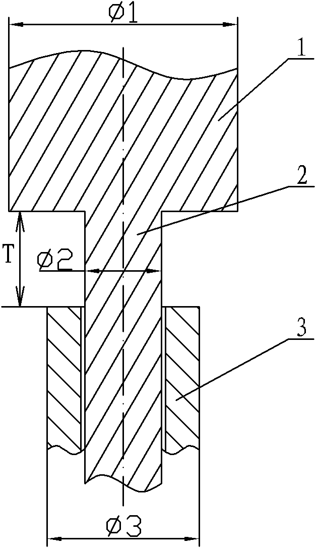
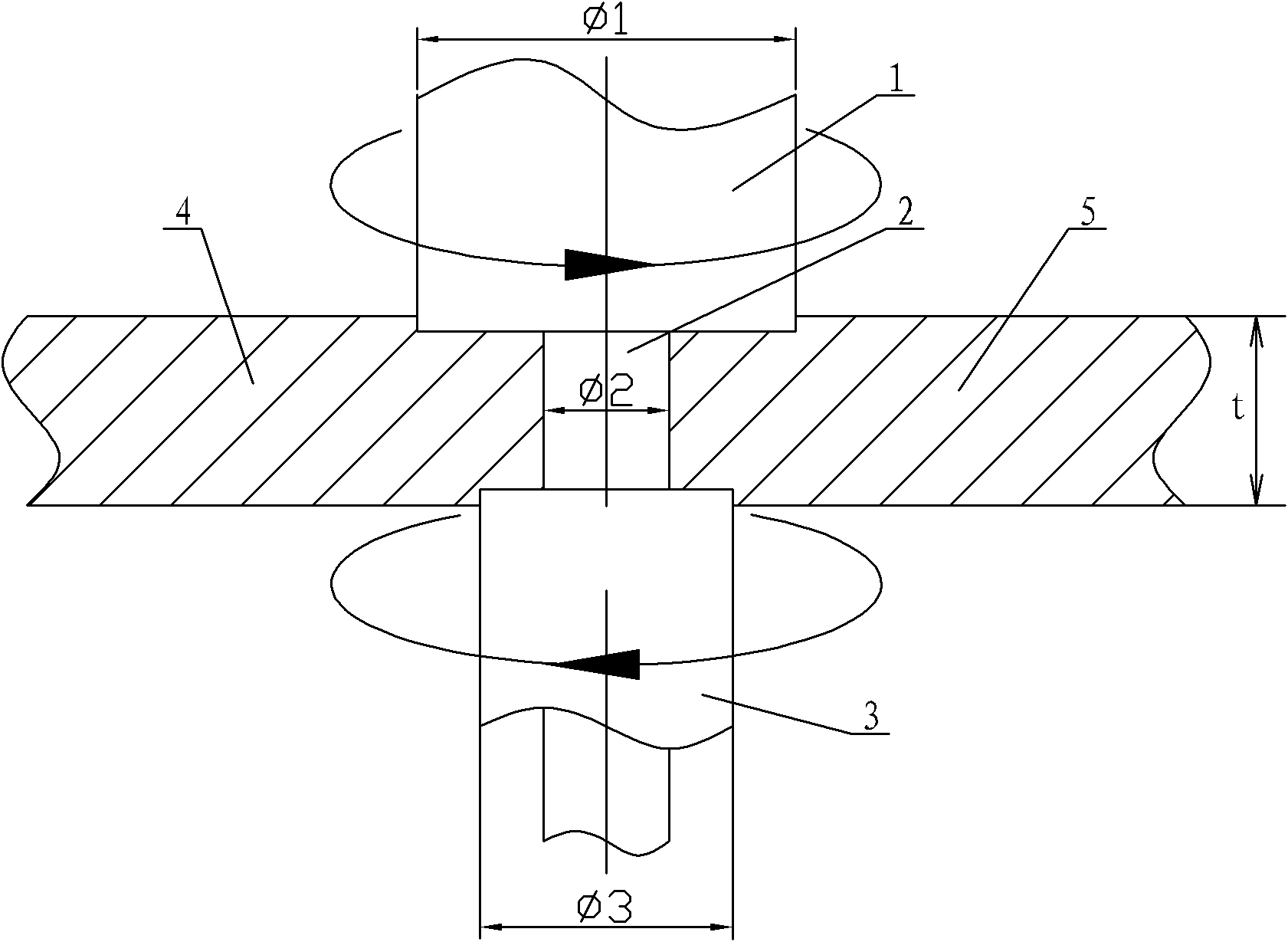
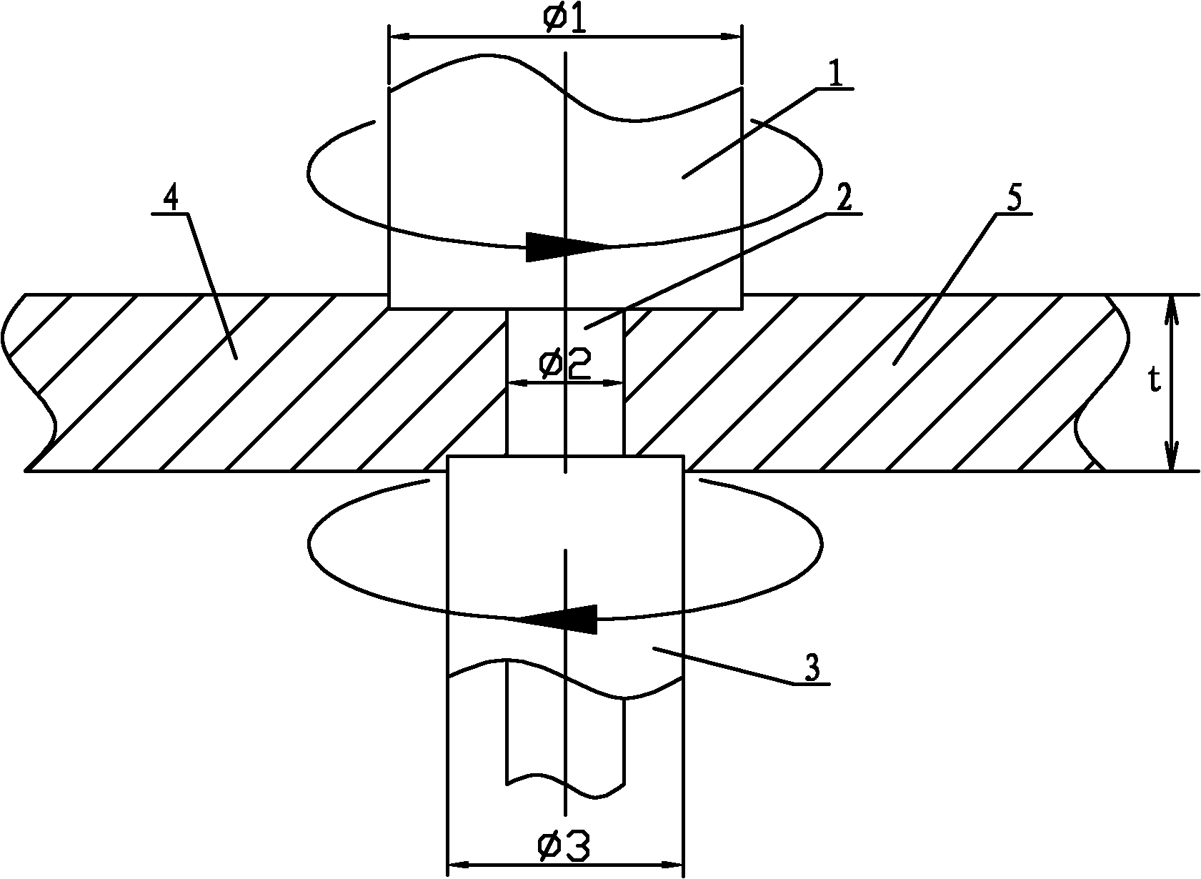
[0012] Specific implementation mode one: combine figure 1 with figure 2 Describe this implementation mode, this implementation mode is realized through the following steps:

[0013] Step 1. Determine the size of the stirring head: according to the thickness t of the first welded workpiece 4 and the second welded workpiece 5, determine the diameter of the upper shoulder φ1, the diameter of the stirring pin φ2 and the diameter of the lower shoulder φ3: the diameter of the upper shoulder φ1 is the 2.8 to 3 times the thickness t of the workpiece to be welded, the diameter φ2 of the stirring pin is 1 to 1.25 times the thickness t of the workpiece to be welded, and the diameter φ3 of the lower shoulder is 2.5 to 2.7 times the thickness t of the workpiece to be welded; according to the first welded workpiece 4 The size of each part of the stirring head is selected according to the thickness of the second workpiece 5 to be welded, so as to ensure the formation of the weld seam and t...

specific Embodiment approach 2

[0018] Specific implementation mode two: combination figure 1 with figure 2 Describe this embodiment, in step 1 of this embodiment, the diameter of the upper shoulder φ1 is three times the thickness t of the workpiece to be welded, the diameter of the stirring pin φ2 is one time the thickness t of the workpiece to be welded, and the diameter of the lower shoulder φ3 is the thickness of the workpiece to be welded 2.8 times the thickness t. The size of the above stirring head can ensure the stability of the weld formation. Other steps are the same as in the first embodiment.

specific Embodiment approach 3

[0019] Specific implementation mode three: combination figure 1 with figure 2 To describe this embodiment, in step 2 of this embodiment, the distance T between the lower end surface of the upper shoulder 1 and the upper end surface of the lower shoulder 3 is 0.3 mm smaller than the thickness t of the workpiece. The above values ​​give the best results for friction stir welding. Other steps are the same as in the first embodiment.


PUM


Abstract

The invention discloses a self-maintained friction stir welding method with reversely rotating upper and lower shaft shoulders, and relates to a self-maintained friction stir welding method to solve the problems that: the upper and lower shaft shoulders have unequal diameters but rotate in the same direction with equal speed, and in the welding process, the weld heat input is large, a workpiece is easy to deform, a mixing needle is inclined to fracture, and the distribution of a weld zone temperature field, a joint structure and residual stress are asymmetric, so that the joint performance is asymmetric, and the bearing capacity of a welding structure is reduced. The method comprises the following steps of: 1, determining the size of a stirring head, namely determining the diameter of the upper shaft shoulder, the stirring needle and the lower shaft shoulder according to the thickness of a first welded workpiece and a second welded workpiece; 2, determining the use length of the stirring needle; 3, fixing the first welded workpiece and the second welded workpiece; 4, positioning the stirring head; and 5, performing friction stir welding on the first welded workpiece and the second welded workpiece, namely integrally forming the upper shaft shoulder and the stirring needle, and allowing the lower shaft shoulder and the upper shaft shoulder to rotate in opposite directions. The self-maintained friction stir welding method is used for self-maintained friction stir welding.

Description

technical field [0001] The invention relates to a self-sustaining friction stir welding method. Background technique [0002] The invention patent application with the patent application number 2010102964802 discloses a "self-sustaining friction stir welding method with different diameters of upper and lower shoulders and its stirring head". The stirring head used in this application is that the diameter of the lower shoulder is smaller than that of the upper shaft The diameter of the shoulder, during the welding process, the rotation direction of the upper shoulder and the lower shoulder is the same, and the two rotate at the same speed, the lower shoulder plays the role of the backing plate of the conventional friction stir welding, but due to the welding process, the lower shoulder It produces a large friction force with the lower surface of the workpiece, which increases the welding heat input, and makes both the workpiece and the stirring pin bear a large torque, which ...

Claims


Application Information

Patent Timeline
Patent Type & Authority Applications(China)
IPC IPC(8): B23K20/12
Inventor 刘会杰侯军才赵运强张超群
Owner HARBIN INST OF TECH
Why Eureka
Try Eureka