Electrophotographic-photosensitive element and method for manufacturing the element, and electrophotographic device using the same

A technology of electrophotography and photoreceptor, which is applied in the fields of optics, electrical recording, instruments, etc., and can solve the problems that cannot be produced, and high-resolution performance cannot be utilized.

Inactive Publication Date: 2011-02-23
FUJI ELECTRIC CO LTD
View PDF3 Cites 4 Cited by
  • Summary
  • Abstract
  • Description
  • Claims
  • Application Information

AI Technical Summary

Problems solved by technology

[0027] Therefore, at present, people cannot make conventional positively charged OPCs that can control the sensitivity similarly to negatively charged OPCs, so the advantages of the high resolution performance of positively charged OPCs themselves cannot be utilized at all.

Method used


Image

  • Electrophotographic-photosensitive element and method for manufacturing the element, and electrophotographic device using the same
  • Electrophotographic-photosensitive element and method for manufacturing the element, and electrophotographic device using the same
  • Electrophotographic-photosensitive element and method for manufacturing the element, and electrophotographic device using the same

Examples


Embodiment

[0097] Embodiments of the present invention are described below

[0098] (Example of Manufacture of Electrophotographic Photoreceptor)

[0099] [conductive substrate]

[0100] Using an aluminum tube, which is cut and machined into a shape with a diameter of 30 mm x 244.5 mm, the surface roughness (R 最大 ) is 0.2, and the wall thickness is 0.75 mm.

[0101] [Preparation of Charge Transport Layer Coating Liquid]

[0102] A styrene-based compound (HTM-A) described below was used as a hole transport material (hereinafter abbreviated as "HTM"), and polystyrene "PS-680" (manufactured by PS Japan Corporation) was used as a binder. A mixture resin, each of which was contained in an amount of 100 parts by weight; these components were dissolved in methylene chloride as a solvent to prepare a charge transport layer coating liquid. Polystyrene usually contains mineral oil, but this can be detrimental to the sensitivity characteristics when used in the binder resin of OPC. On the othe...

experiment Embodiment 1-7

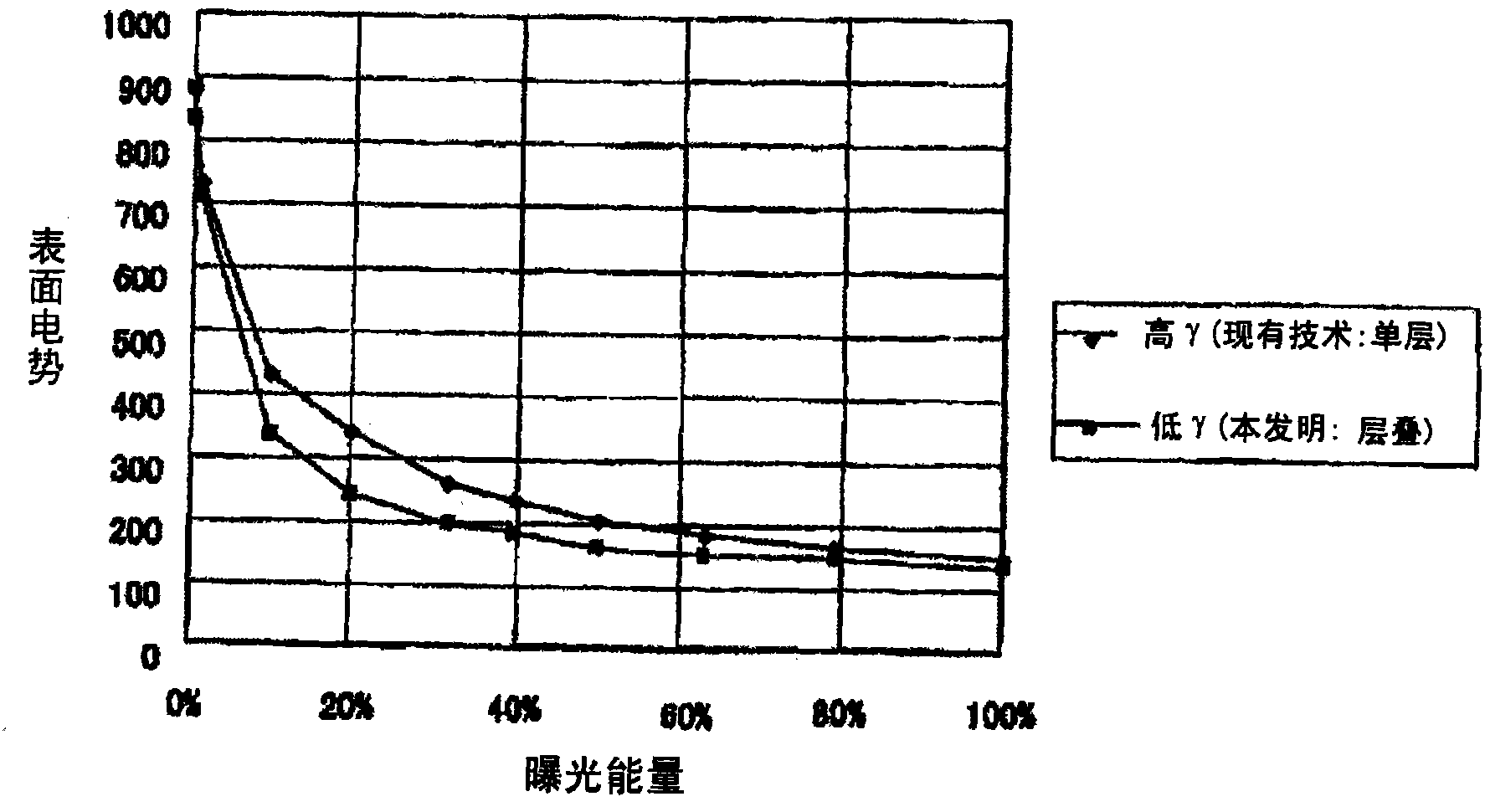
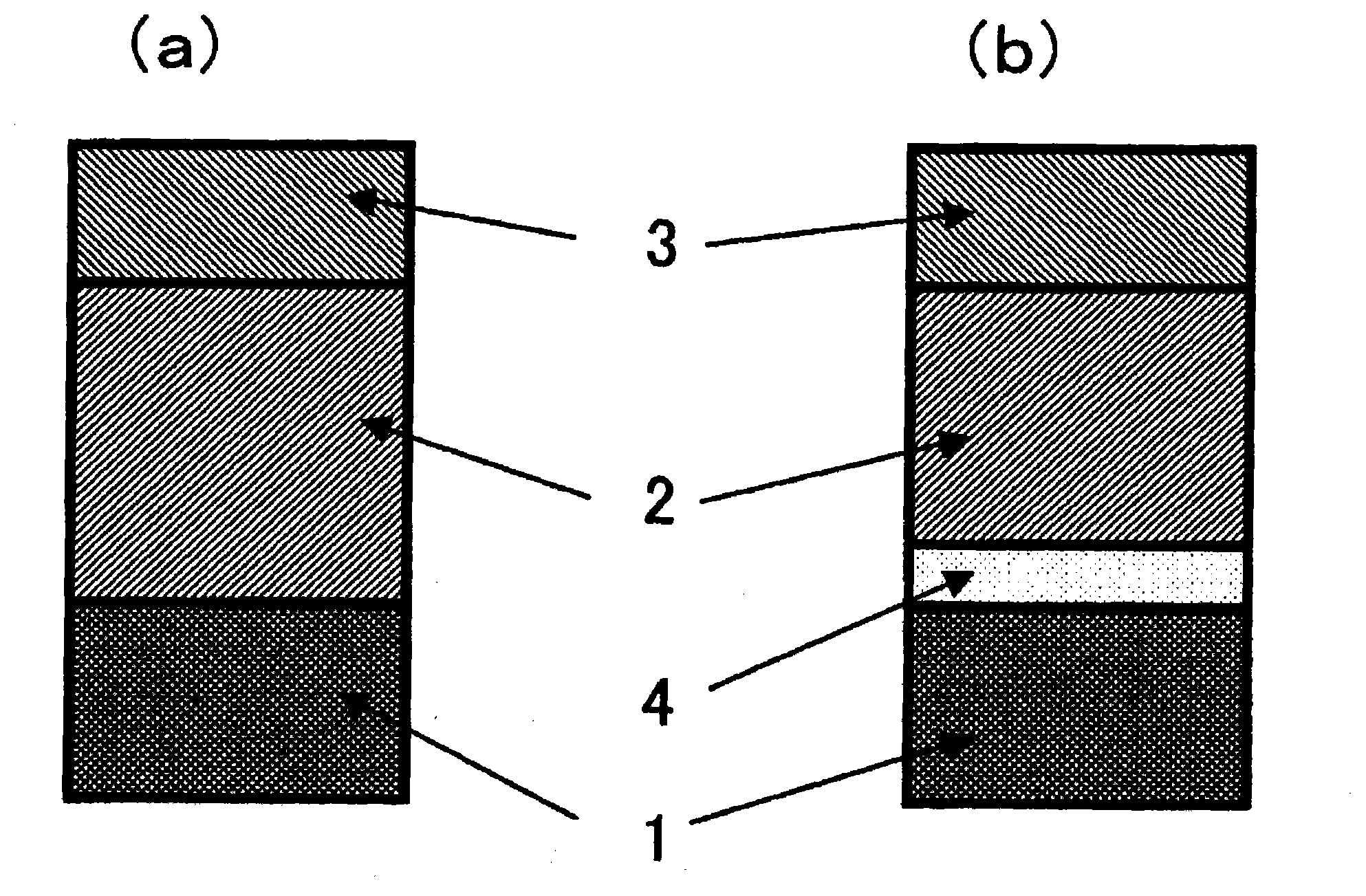
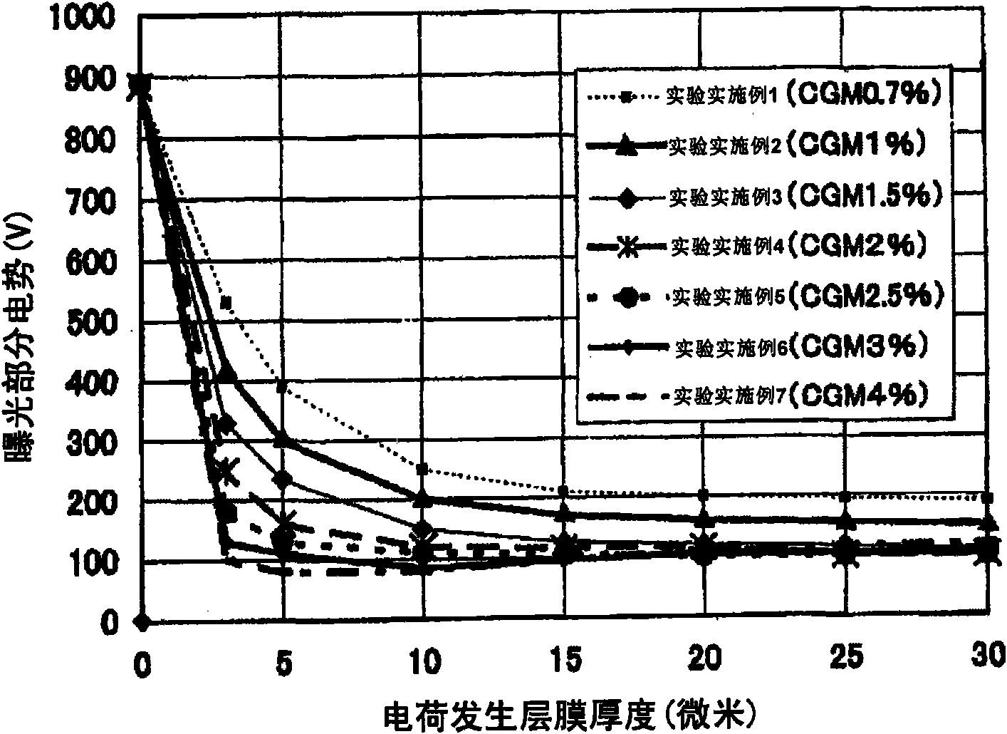
[0113] As shown in Table 1 below, various stacked positively charged OPCs were manufactured, and the charge-generating material addition amount in the charge-generating layer of Experimental Examples 1-7 was varied in the range of 0.7-4% by weight. In Experimental Examples 2-5 of the present invention, the charge generating material was added in an amount of 1 wt%, 1.5 wt%, 2 wt% and 2.5 wt% in the positively charged laminated OPC. In the experimental example, the film thickness of the charge transport layer was set to 3 microns, 5 microns, 10 microns, 15 microns, 20 microns, 25 microns and 30 microns, and the total film thickness including the charge transport layer was fixed at 30 micron photoreceptor.

[0114] These photoreceptors were mounted in a Brother Industries "HL5240" model 1200 DPI high-resolution printer using a non-magnetic one-component contact development detergent-free process using suspension-polymerized toner, 30 ppm (A4 equivalent), Measure the potential o...


PUM


Abstract

Provided are an electrophotographic-photosensitive element and an electrophotographic device, which are used in a high speed / resolution color machine of a positively charging type and which are excellent in dot-reproducibility and graduation. Also provided is an electrophotographic-photosensitive element, which can realize the optimum sensitivity characteristics for each device merely by adjusting the film thickness percentage. The electrophotographic-photosensitive element is positively charged into a laminated type by laminating a charge transport layer, which includes a positive hole transport material and a first adhesive resin, and a charge generating layer, which includes a charge generating material, a positive hole transport material and a second adhesive resin, sequentially on a conductive base member. The contents of the charge generating material in the charge generating layer are within a range over 0.7 wt. % and below 3.0 wt. % in the same layer.

Description

technical field [0001] The present invention relates to an electrophotographic photoreceptor having excellent charging characteristics and independent dot reproducibility, which can be made to have optimum photosensitivity, can obtain optimum image quality, and is used for a belt having high resolution and high speed. An electrophotographic device of a positive charge system, the present invention also relates to a method of manufacturing the electrophotographic photoreceptor, and an electrophotographic device using the electrophotographic photoreceptor. Background technique [0002] In the prior art, printers, facsimile machines, copiers and other imaging devices using electrophotography all include: a photoreceptor, which is an image carrier; a charging device, which uniformly charges its surface; an exposure device, which writes an electric image (electrostatic latent image); a developing device that develops the latent image by using a toner to form a toner image; and a ...

Claims


Application Information

Patent Timeline
Patent Type & Authority Applications(China)
IPC IPC(8): G03G5/05G03G5/047G03G5/147G03G9/087
CPCG03G5/0616G03G5/047G03G5/0535
Inventor 北川清三中村洋一江森弘田中靖一柳洋幸
Owner FUJI ELECTRIC CO LTD
Why Eureka
Try Eureka