Improved two-stage regeneration method and equipment for catalytic cracking catalyst

A technology for catalytic cracking and regeneration equipment, which is applied in the direction of catalyst regeneration/reactivation, physical/chemical process catalysts, chemical instruments and methods, etc., and can solve problems such as high gas velocity in the coking section of the bed, low catalyst concentration, and destruction of pressure balance , to achieve stable control of the reaction temperature, reduce energy consumption, and improve the effect of operation

Active Publication Date: 2013-06-05
PETROCHINA CO LTD +2
View PDF3 Cites 0 Cited by
  • Summary
  • Abstract
  • Description
  • Claims
  • Application Information

AI Technical Summary

Problems solved by technology

Although the gas-solid contact effect of the charred tube is better, its catalyst concentration is lower. In order to achieve the same regeneration effect, a larger height is required, which may destroy the pressure balance with the reaction system and cause catalyst circulation problems.
On the other hand, in this method, the gas velocity in the coking section of the bed layer is too high, which may cause the problem of catalyst loss
[0010] In summary, there is still a lot of room for improvement in the existing two-stage regeneration method and equipment for catalytic cracking coke tanks

Method used


Image

  • Improved two-stage regeneration method and equipment for catalytic cracking catalyst
  • Improved two-stage regeneration method and equipment for catalytic cracking catalyst
  • Improved two-stage regeneration method and equipment for catalytic cracking catalyst

Examples


Embodiment 1

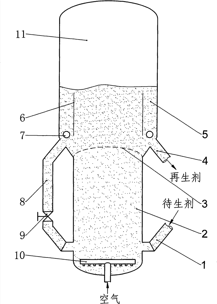
[0038] figure 1 A specific structure of the catalytic cracking two-stage regeneration equipment of the present invention is shown. As shown in the figure, when the catalytic cracking two-stage regeneration equipment of this embodiment utilizes the catalytic cracking two-stage regeneration equipment of the present invention to perform coke regeneration of the catalyst, the coke-containing standby catalyst (spent catalyst) passes through the standby standpipe 1 From the bottom of the burnt pot regenerator 2, it enters the burnt pot regeneration section (that is, the first stage of the burnt pot regenerator), the superficial gas velocity is 1.0-3.0m / s, the operating temperature is 630-740°C, and the residence time of the catalyst is 0.5~1.2min. A main wind enters the bottom of the first-stage coke tank regenerator evenly from the gas distributor 10, and its flow rate accounts for 85-99% of the total main air flow of the regenerator, and the coke on the standby agent burns with t...

Embodiment 2

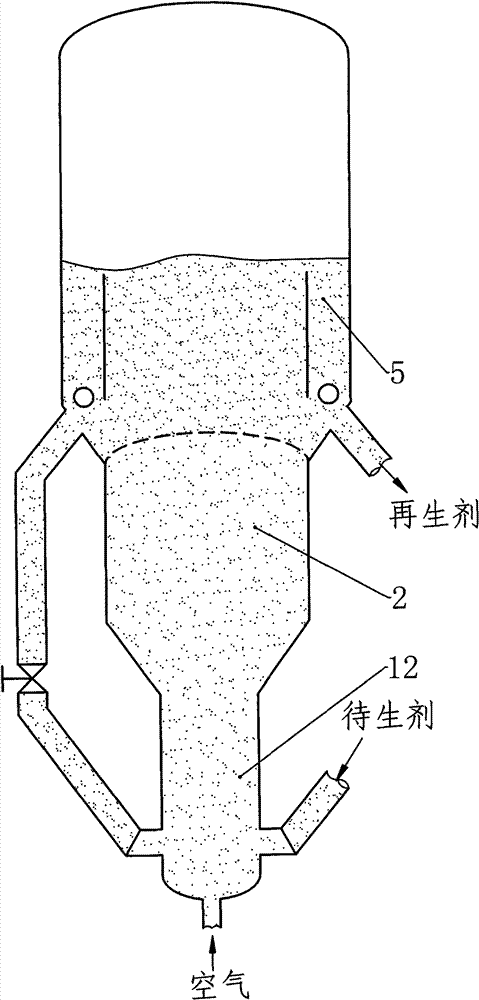
[0041] figure 2 An embodiment of another technical solution of the present invention is shown. The difference from Example 1 is that a dilute-phase conveying pipe 12 is installed at the bottom of the burnt tank regenerator 2, and its gas velocity is 3-7m / s. The catalyst transported by the catalyst circulation pipe 8 of the layer regenerator first enters the bottom of the dilute phase transport pipe 12 and then enters the coke tank 2 together. Due to the high gas velocity in the dilute-phase conveying pipe 12, the turbulent intensity of the particles is relatively high, which is conducive to better contact heat exchange between the two streams of catalysts.


PUM


Abstract

The invention provides an improved two-stage regeneration method and equipment for catalytic cracking catalyst. The equipment comprises a regeneration section of a scorched jar and a regeneration section of a dense-phase circulation bed, which are arranged in series. In the invention, carbon coke-containing catalyst to be generated is introduced into the regeneration section of the scorched jar from the bottom of the regeneration section of the scorched jar, and is contacted with the main wind of the scorched jar to generate combustion reaction to generate smoke; the generated smoke and the catalyst carried by the generated smoke ascend into the regeneration section of the dense-phase circulation bed through a porous plate-type distributor at the top of the regeneration section of the scorched jar; different superficial gas velocities in the central region and the outer ring region of the regeneration section of the dense-phase circulation bed are controlled to lead the catalyst particles to form internal circular flow between the two regions to obtain efficient regeneration; and a part of the dense-phase circulation bed catalyst circularly enters into the bottom of the regeneration section of the scorched jar, so as to improve the temperature and particle concentration of the regeneration section of the scorched jar. The method and the equipment provided by the invention havethe advantages of improving gas-solid contact, enhancing the utilization efficiency of the main wind, and lowering the energy consumption of the equipment.

Description

technical field [0001] The invention belongs to the technical field of petrochemical industry, and in particular relates to an improved two-stage regeneration method of catalytic cracking catalyst and regeneration equipment (regenerator) for realizing the regeneration method. Background technique [0002] The catalytic cracking process is one of the most important means of lightening heavy raw materials in modern oil refineries. It uses catalysts to crack heavy macromolecular petroleum hydrocarbons into high-value small molecule transportation fuels and chemical raw materials. This process usually uses molecular sieve acidic catalysts. After the heavy oil reacts in the riser, in addition to generating light hydrocarbons, a part of coke is deposited on the surface of the catalyst, resulting in a decrease in catalyst activity. Therefore, oxygen-containing gas (usually air) must be introduced to burn off this part of coke to restore catalyst activity. This process is usually ca...

Claims


Application Information

Patent Timeline
Patent Type & Authority Patents(China)
IPC IPC(8): B01J8/00B01J38/02
Inventor 张永民卢春喜刘英聚丛森滋李胜山张星孙方宪张新国韩玉梅宫海峰
Owner PETROCHINA CO LTD
Why Eureka
Try Eureka