Sidewall structure of roasting furnace

A technology of side wall structure and roasting furnace, which is applied in the direction of integral lining, etc., can solve the problems of increasing fuel consumption, difficulty in temperature regulation, and increasing fuel input in the side fire channel, and achieves simplified temperature regulation measures, guaranteed strength, and simple construction technology. Effect

Inactive Publication Date: 2011-03-09
五矿二十三冶建设集团有限公司
View PDF7 Cites 2 Cited by
  • Summary
  • Abstract
  • Description
  • Claims
  • Application Information

AI Technical Summary

Problems solved by technology

In order to keep the quality of roasted products consistent, it is objectively required that the temperature of the furnace chamber of the side fire channel and the middle fire channel should also be kept basically the same, so it is necessary to increase the fuel input of the side fire channel to increase the furnace temperature of the furnace chamber near the side fire channel , which will increase fuel consumption and temperature adjustment difficulty accordingly

Method used


Image

  • Sidewall structure of roasting furnace
  • Sidewall structure of roasting furnace
  • Sidewall structure of roasting furnace

Examples


Embodiment 1

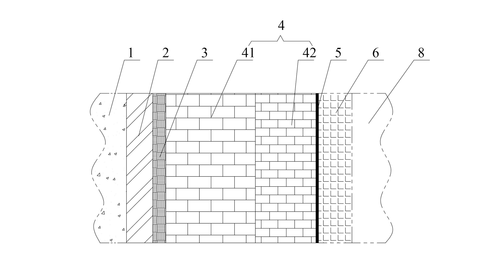
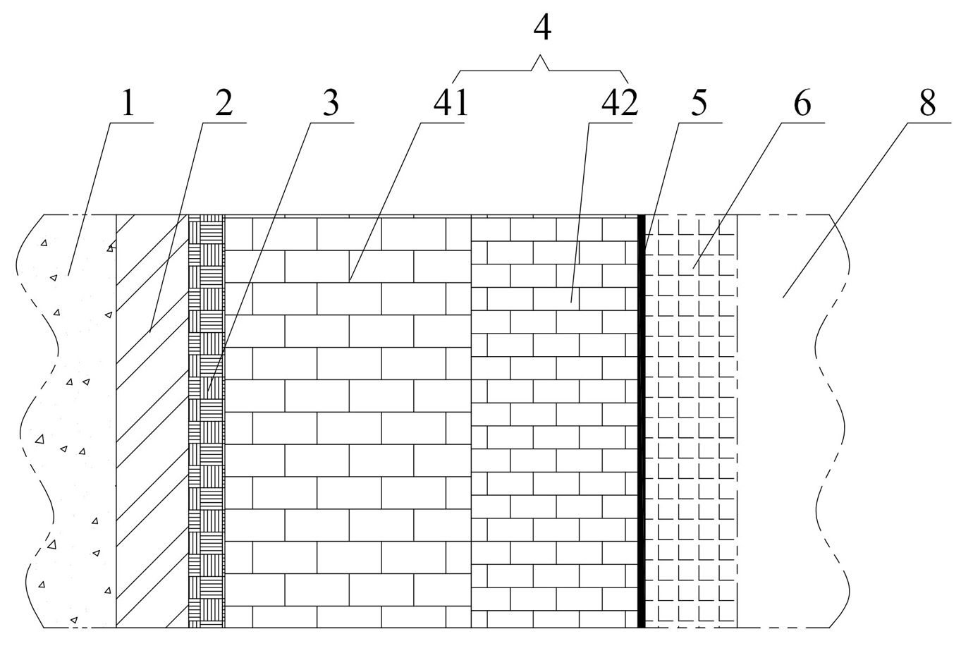
[0020] a kind of like figure 1 The side wall structure of the shown roasting furnace of the present invention, the side wall structure comprises the silicate plate layer 2 close to the inner side of the roasting furnace shell 1 and the refractory mud filler layer close to the outer side of the burning furnace side fire channel 6 5. The inner side of the side fire channel 6 is a material box 8 for placing roasted materials; the middle part from the inner side of the silicate plate layer 2 to the outer side of the refractory mud filler layer 5 is also provided with a silicate fiber layer 3 and a thermal insulation brick layer in turn. 4. The insulating brick layer 4 is composed of a diatomite insulating brick layer 41 close to the inner side of the silicate fiber layer 3 and a high alumina insulating brick layer 42 close to the outer side of the refractory mud filler layer 5 . The silicate plate layer 2 in this embodiment is filled with aluminum silicate plate, and the silicate...

Embodiment 2

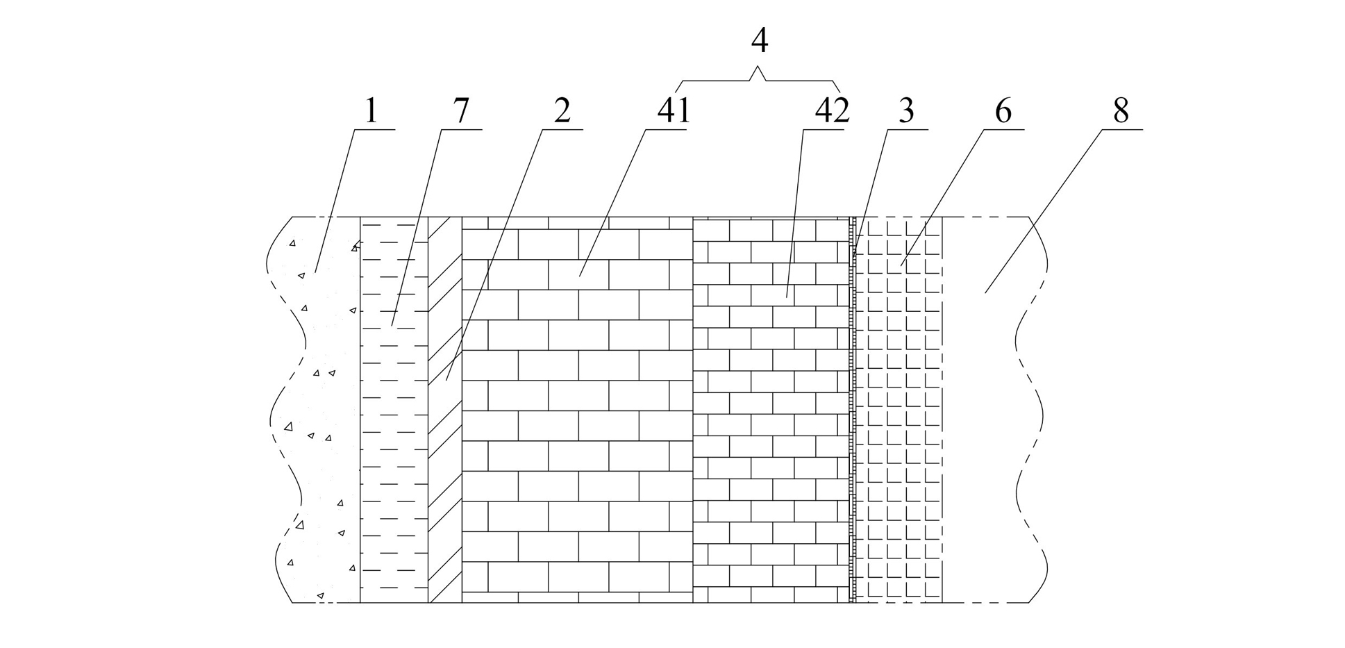
[0024] a kind of like figure 2 The side wall structure of the roasting furnace shown in the present invention, the side wall structure includes the insulation castable layer 7 close to the inner side of the roasting furnace shell 1 and the silicate fiber layer close to the outer side of the roasting furnace side fire channel 6 3. The inner side of the side fire channel 6 is the material box 8 for placing the roasted materials; the middle part from the inner side of the thermal insulation castable layer 7 to the outer side of the silicate fiber layer 3 is also provided with a silicate plate layer 2 and a thermal insulation brick layer in sequence. 4. The insulating brick layer 4 is composed of a diatomite insulating brick layer 41 close to the inner side of the silicate plate layer 2 and a high alumina insulating brick layer 42 close to the outer side of the silicate fiber layer 3 . The silicate plate layer 2 in this embodiment is filled with calcium silicate boards, and the ...


PUM

PropertyMeasurementUnit
thicknessaaaaaaaaaa
thicknessaaaaaaaaaa
thicknessaaaaaaaaaa

Abstract

The invention discloses a sidewall structure of a roasting furnace, which comprises a silicate plate layer and a refractory clay packing layer, wherein the silicate plate layer abuts against the furnace shell of the roasting furnace, the refractory clay packing layer abuts against the side flame path of the roasting furnace; and a silicate fiber layer and an insulating brick layer are orderly arranged between the silicate plate layer and the refractory clay packing layer. The invention discloses another sidewall structure of a roasting furnace, which comprises an insulating pouring material layer and a silicate fiber layer, wherein the insulating pouring material layer abuts against the furnace shell of the roasting furnace, the silicate fiber layer abuts against the side flame path of the roasting furnace, and a silicate plate layer and an insulating brick layer are orderly arranged between the insulating pouring material layer and the silicate fiber layer. The sidewall structure of the invention has the advantages of high strength, favorable insulating property, high universality, strong practicality and the like, and is convenient in construction.

Description

technical field [0001] The invention relates to a component structure of a furnace and a kiln, in particular to a component structure of a furnace lining part of a firing furnace. Background technique [0002] The existing roasting furnace includes the furnace shell (the furnace shell is generally a concrete retaining wall), the side wall and the furnace chamber in sequence from the outside to the inside. The furnace chamber near the side wall is provided with a side fire channel, and there are multiple side fire channels in the side fire channel. The middle fire path, in the middle of each fire path is a material box for placing roasted materials. [0003] In the existing roasting furnace, there is a gap of 1mm~2mm at the junction of the side flue and the side wall, because during the use of the roasting furnace, as the temperature of the furnace chamber rises, the flue wall will produce A certain amount of expansion, the gap is an expansion joint specially reserved for th...

Claims


Application Information

Patent Timeline
Patent Type & Authority Applications(China)
IPC IPC(8): F27D1/10
Inventor 周湘金
Owner 五矿二十三冶建设集团有限公司
Why Eureka
Try Eureka