Silicon controlled chopping power regulation driving device

A driving device and waveform technology, applied in the direction of output power conversion device, AC power input conversion to DC power output, electrical components, etc., can solve the problems of high cost and low accuracy

Active Publication Date: 2011-03-09
浙江瑞德电子科技有限公司
View PDF4 Cites 4 Cited by
  • Summary
  • Abstract
  • Description
  • Claims
  • Application Information

AI Technical Summary

Problems solved by technology

However, the phase shift range of the current hardware phase shift power modulation circuit can only be less than 90 degrees, that is, the power adjustment range can only be within the range between 50% and 100% of the output power
And the single-chip software power adjustment can output the full power range of 0%-100%, but the implementation cost of the single-chip software solution is relatively high, and the accuracy is not high

Method used


Image

  • Silicon controlled chopping power regulation driving device
  • Silicon controlled chopping power regulation driving device
  • Silicon controlled chopping power regulation driving device

Examples


Embodiment Construction

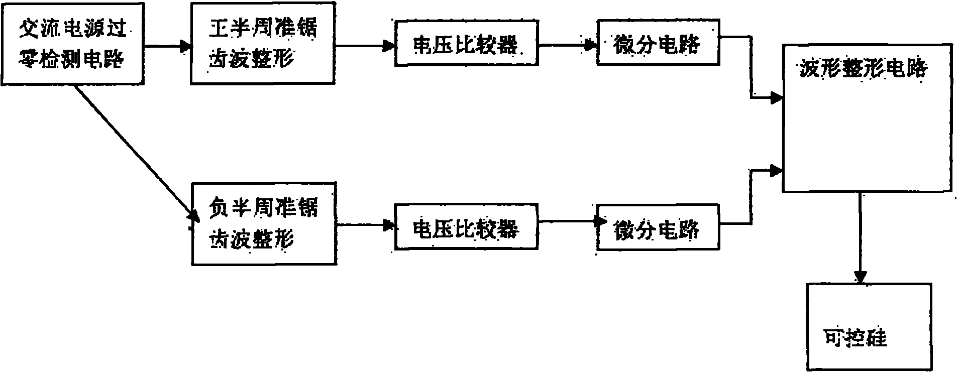
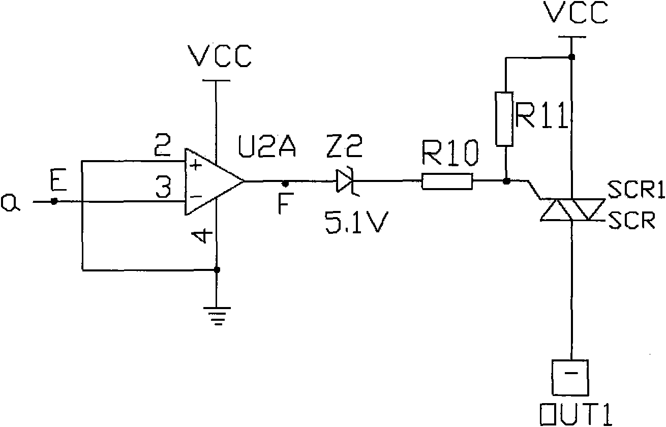
[0020] Example: see Figure 1~4 As shown, a thyristor chopper power regulation drive device includes a thyristor SCR1, which consists of an AC power zero-crossing detection circuit, a quasi-sawtooth wave shaping circuit, a voltage-time converter, a differential circuit, a waveform shaping circuit and a controllable Silicon Scr1 composition;

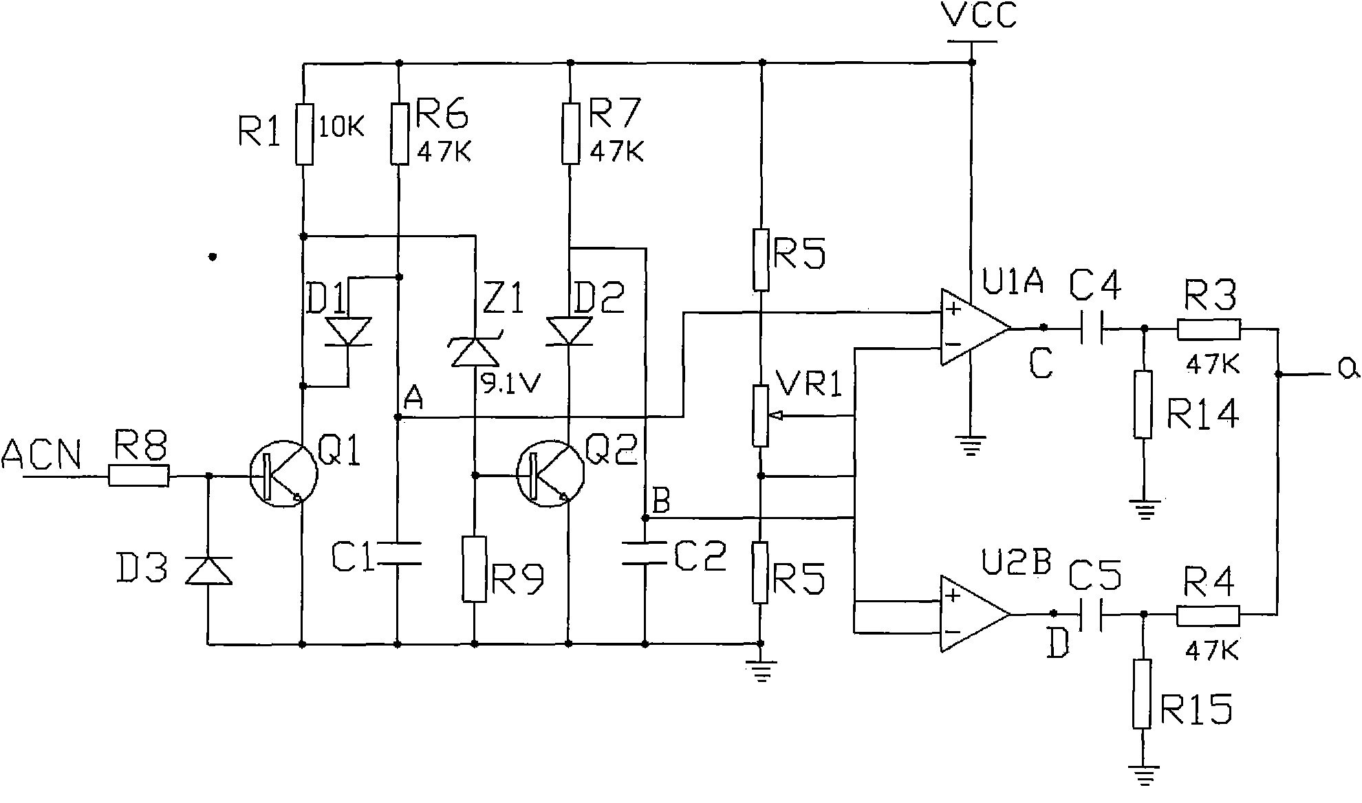
[0021] The AC power zero-crossing detection circuit consists of the first triode Q1, the second triode Q2 and their peripheral components. The first resistor R1, the eighth resistor R8, the ninth resistor R9, the first diode D1, and the second diode tube D2, the third diode D3, and the first Zener diode Z1;

[0022] The quasi-sawtooth wave shaping circuit is composed of a first capacitor C1, a second capacitor C2, a sixth resistor R6, and a seventh resistor R7;

[0023] The voltage-time converter is composed of a first comparator U1A, a second comparator U2B, a second resistor R2, a fifth resistor R5, and a potentiometer VR1;

[0024] ...


PUM


Abstract

The invention relates to a silicon controlled chopping power regulation driving device, wherein the power frequency signals of a power supply pass through the eighth resistor of an alternating current power supply zero-crossing detection circuit to be input, the signals pass through a first triode and a second triode to generate a positive semicircle standard sawtooth wave and a negative semicircle standard sawtooth wave of which inclined planes are towards the left; the positive semicircle standard sawtooth wave and the negative semicircle standard sawtooth wave pass through the first comparator and second comparator of a voltage-time converter to be converted to a positive semicircle standard sawtooth rectangular wave and a negative semicircle standard sawtooth rectangular wave; the positive and negative semicircle standard sawtooth rectangular waves pass through a differential circuit so that the waveforms of the positive and negative semicircle standard sawtooth rectangular waves are combined; and the third voltage comparator of a waveform shaping circuit is used to perform waveform shaping again, and the shaped waveform drives a silicon controlled rectifier to output choppingsignals. The driving device of the invention realizes the characteristics of low cost, high output efficiency, wide power regulating range, high regulating fineness, easy modularizaion process and the like. The driving device is particularly suitable for the application fields which require power regulating, have simple functions and are sensitive to the cost, such as motor speed regulating and desk lamp brightness regulating.

Description

Technical field: [0001] The invention relates to the technical field of thyristor control, in particular to a thyristor power-adjusting driving device, and is particularly suitable for the thyristor power-adjusting driving device used for motor speed regulation and table lamp brightness adjustment. Background technique: [0002] At present, the application of thyristor phase modulation to adjust power is very common. The characteristic of adjusting power with this method is that it can obtain relatively high energy output efficiency. At present, this method of power adjustment can be divided into two types, one is hardware shifting Phase modulation technology, the other is to rely on single-chip software control to achieve chopping power adjustment. However, the phase shifting range of the current hardware phase-shifting and power-modulating circuit can only be less than 90 degrees, that is, the power adjustment range can only be within the range between 50% and 100% of the ...

Claims


Application Information

Patent Timeline
Patent Type & Authority Applications(China)
IPC IPC(8): H02M1/08H02M7/497
Inventor 潘卫明姚继能谢辉曾飞熊
Owner 浙江瑞德电子科技有限公司
Why Eureka
Try Eureka