
Multi-channel dual-functional wave multiplexing photoelectric integrated module

A wavelength division multiplexing, optoelectronic integration technology, applied in wavelength division multiplexing systems, optical guides, optics, etc., can solve the problems of large insertion loss, difficult to integrate, large insertion loss, etc., and achieve low insertion loss and compact structure. , the effect of low cost

Active Publication Date: 2011-03-09
AOC TECH (WUHAN) CO LTD
View PDF4 Cites 9 Cited by
  • Summary
  • Abstract
  • Description
  • Claims
  • Application Information

AI Technical Summary

Problems solved by technology

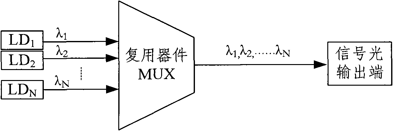
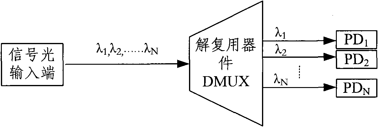
Therefore, the WDM in the prior art can only realize one function of multiplexing or demultiplexing at a time, and in some special occasions, such as modules such as optical amplifiers, devices with two functions of splitting and combining are needed. Two wavelength division multiplexers are required, and many optical fibers are required to be connected to each other. Since the minimum bending radius of each optical fiber connection is 25mm, such as Figure 10 As shown, the optical fiber includes an optical fiber cladding 11 and an optical fiber core 12. If the bending radius of the optical fiber is less than 25 mm, the signal light transmitted in the optical fiber core 12 will not satisfy the principle of total reflection, and the signal light will be distorted when transmitted in the optical fiber. , and part of the light energy is lost
At the same time, if the bending radius is less than 25mm, the optical fiber is easily damaged, which will cause distortion of the optical signal and increase the insertion loss
In addition, because there are optical fibers in the optical component system, it will take up a lot of space, which will undoubtedly increase the cost
Since the traditional free-space optical element system for wavelength division multiplexing and demultiplexing includes collimators and fiber optic heads, many components are used, so the insertion loss is large and it is not easy to integrate

Method used


Image

  • Multi-channel dual-functional wave multiplexing photoelectric integrated module
  • Multi-channel dual-functional wave multiplexing photoelectric integrated module
  • Multi-channel dual-functional wave multiplexing photoelectric integrated module

Examples


Embodiment Construction

[0020] In order to facilitate a further understanding of the structure and achieved effects of the present invention, preferred embodiments are described in detail below in conjunction with the accompanying drawings.

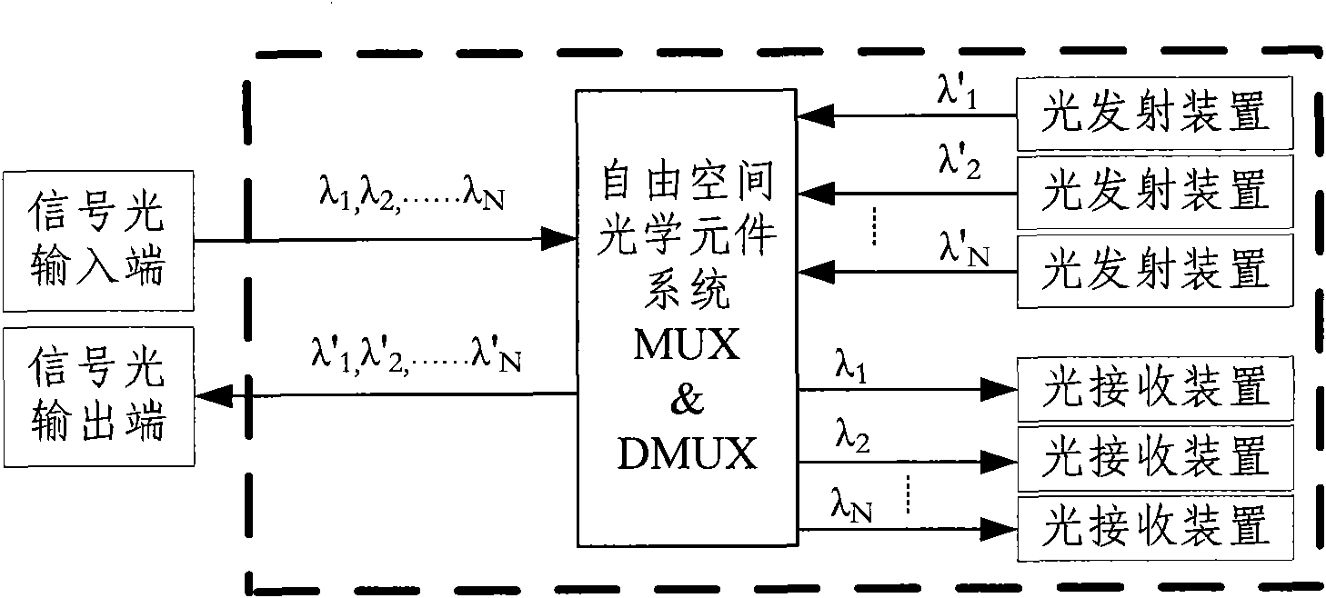
[0021] Such as Figure 4 As shown, the multi-channel dual-function wavelength division multiplexing optoelectronic integrated module of the present invention includes a signal light input terminal 1, a signal light output terminal 2, at least two light emitting devices 3 for emitting signal light, and light The light receiving device 4 for detecting signal light with the same number of emitting devices 3 and the light receiving device 4 for transmitting signal light in two directions between the signal light input end 1 and the signal light output end 2 and the light emitting device 3 and light receiving device 4 Free Space Optics System 10 . Such as Figure 4 and Figure 5 As shown, the free-space optical element system 10 includes a group of multi-wavelengt...


PUM


Abstract

The invention discloses a multi-channel dual-functional wave multiplexing photoelectric integrated module. The module comprises a signal light input end, a signal light output end, at least two light emitting devices for emitting signal light, light receiving devices with the same number as the light emitting devices and used for detecting the signal light, and free spatial optical element systems positioned between the signal light input end and the signal light output end and between the light emitting devices and the light receiving devices and used for transmitting the signal light in two directions. The multi-channel dual-functional wave multiplexing photoelectric integrated module can realize dual functions of multiplexing and de-multiplexing, integrates light and electricity, has no interconnection of fibers, has low cost, compact structure, small occupation space and low insertion loss, saves optical devices, and can be applied to more places.

Description

technical field [0001] The invention relates to an optoelectronic integrated module, in particular to a multi-channel dual-function wavelength division multiplexing optoelectronic integrated module capable of realizing the dual functions of multiplexing and demultiplexing without optical fiber connection. Background technique [0002] At the end of an optical communication system, a wavelength division multiplexer is usually used, which can send signal light converted from an electrical signal to an optical transmission path such as an optical fiber, or the wavelength division multiplexer receives signal light from an optical transmission path . In the prior art, a wavelength division multiplexer is a wavelength division or multiplexing device, which can multiplex optical signals of different wavelengths onto one optical fiber, or multiplex multiple optical signals in one optical fiber separated by wavelength. At present, in a wavelength division multiplexing (WDM, Wave Di...

Claims


Application Information

Patent Timeline
Patent Type & Authority Applications(China)
IPC IPC(8): H04J14/02G02B6/42G02B6/293
Inventor 顾共恩赵兰兰朱益清邱二虎苏超
Owner AOC TECH (WUHAN) CO LTD
Learn More