Active safeguard system and method for floating-roof oil tank

An oil storage tank, active safety technology, applied in containers, packaging, fire rescue and other directions, can solve the problems of aggravating floating roof load, large-scale burning of oil, difficult to clean, etc., to achieve reduced possibility, strong fluidity, and response time short effect

Active Publication Date: 2011-03-16
VITALONG FIRE SAFETY GRP
View PDF8 Cites 26 Cited by
  • Summary
  • Abstract
  • Description
  • Claims
  • Application Information

AI Technical Summary

Problems solved by technology

[0006] 2. The sprayed foam first gathers between the tank wall and the foam weir plate, and it takes about 9 minutes to be fully collected. After that, the foam can enter the primary and secondary seals and start to extinguish the fire. Time delay will cause large-scale combustion of the oil and increase It eliminates the possibility of another explosion or continuous explosion at the sealed place, which expands the disaster situation
[0007] 3. The poor fluidity of the foam makes the fire extinguishing efficiency low
[0008] 4. After the fire is extinguished, a large amount of foam gathers on the floating roof and is not easy to clean up, which will increase the load on the floating roof and even cause the roof to sink

Method used


Image

  • Active safeguard system and method for floating-roof oil tank
  • Active safeguard system and method for floating-roof oil tank
  • Active safeguard system and method for floating-roof oil tank

Examples


Embodiment 1

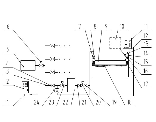
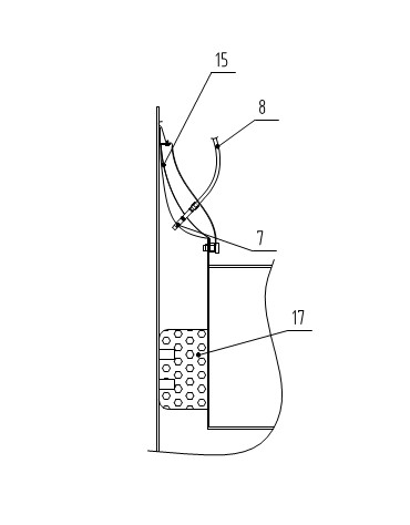
[0028] An active safety protection system for an external floating roof oil storage tank, such as figure 1 As shown, it includes: control line 1, control cabinet 2, pipeline 3, manual valve 4, carbon dioxide storage device 5, master control valve 6, carbon dioxide special nozzle 7, metal hose 8, outer floating roof 9, oil and gas filtration and recovery device 10. Gas detection and analysis device 11, oil storage tank 12, gas pipe for oil and gas recovery 13, gas pipe for detection and analysis 14, secondary seal 15, suction joint 16, primary seal 17, crude oil 18, one-way valve 19, regulating valve 20 , flow meter 21, carbon dioxide inerting device 22, inerting electric valve 23, fire extinguishing electric valve 24. in:

[0029] The active safety protection system of the external floating roof oil storage tank can control one or more oil storage tanks 12, and arrange the control cabinet 2 in a reasonable position for manual operation. The equipment involved is remotely con...

Embodiment 2

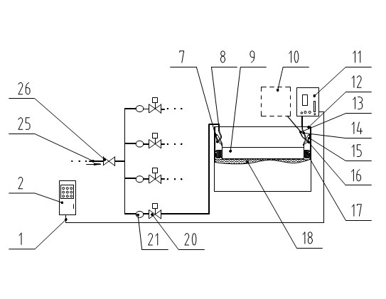
[0036] An active safety protection system for an external floating roof oil storage tank, such as figure 2 As shown, the difference from Embodiment 1 is that the pipeline 3, manual valve 4, carbon dioxide storage device 5, master control valve 6, check valve 19, carbon dioxide inerting device 22, inerting electric motor Valve 23 and fire extinguishing electric valve 24, and increased external carbon dioxide gas pipeline 25, external carbon dioxide pipeline valve 26. Embodiment 2 does not provide carbon dioxide gas from the carbon dioxide storage device 5 and the carbon dioxide inerting device 22, but uses the carbon dioxide gas generated in other processes, and transports it to the external floating roof through the external carbon dioxide gas pipeline 25 and the external carbon dioxide pipeline valve 26 The annular space between the primary and secondary seals of type petroleum storage tank 12.


PUM


Abstract

The invention discloses an active safeguard system and method for a floating-roof oil tank. Carbon dioxide gas serving as an inerting agent is filled into an annular spaced formed among the primary and secondary seals as well as tank walls of the floating-roof oil tank, the oxygen content and combustible mixed gas content in the annular space are controlled within a specified range, and the original dangerous space of fire disaster is turned into an inert safeguarding space which is prevented from explosion and combustion. The invention has the following advantage: the problem that the floating-roof oil tank is susceptible to oil gas explosion caused by lightning strike, static and the like in the annular space is solved.

Description

technical field [0001] The invention relates to a fire safety protection system, in particular to an active safety protection system and a protection method for an external floating roof oil storage tank. Background technique [0002] Crude oil is a flammable and explosive dangerous product. There are many ways to store crude oil, but the oil storage tank with external floating roof has become the most commonly used storage tank at present. Due to the existence of primary and secondary sealing devices between the edge of the floating roof of the external floating roof oil storage tank and the inner wall of the tank, a mixture of explosive gas and oxygen appears for a long time between the primary and secondary sealing, and this space belongs to the explosion hazard area. Apart from man-made reasons, it is easy to cause an oil and gas explosion in this sealed space due to the influence of lightning, static electricity generated by the storage tank itself, sparks and other fac...

Claims


Application Information

Patent Timeline
Patent Type & Authority Applications(China)
IPC IPC(8): B65D90/22A62C3/06A62C31/00
Inventor 汪映标
Owner VITALONG FIRE SAFETY GRP
Why Eureka
Try Eureka