Semi-coaxial resonator and filter device

A coaxial resonator and resonator technology, applied in resonators, waveguide devices, electrical components, etc., can solve the problems of resonator Q value reduction, high manufacturing cost, Q value reduction, etc., and the Q value will not be reduced , Low manufacturing cost, and the effect of suppressing fluctuations

Inactive Publication Date: 2011-03-23
TAMAGAWA ELECTRONICS
View PDF1 Cites 12 Cited by
  • Summary
  • Abstract
  • Description
  • Claims
  • Application Information

AI Technical Summary

Problems solved by technology

Therefore, there is a problem that the structure becomes complicated and the manufacturing cost is large, etc.
[0009] Moreover, since the resonator is installed on the housing wall in such a way that the resonator is at right angles to the housing wall, there is a problem that the skin current of the resonator concentrates on the corner of the resonator standing upright from the housing wall and the Q value decreases.
In addition, if the gap between the resonator and the case wall is narrowed in order to reduce the size of the resonator, the tip capacitance increases, so the length of the resonator has to be shortened in order to maintain a predetermined resonance frequency. The problem of lower Q value

Method used


Image

  • Semi-coaxial resonator and filter device
  • Semi-coaxial resonator and filter device
  • Semi-coaxial resonator and filter device

Examples


no. 1 approach

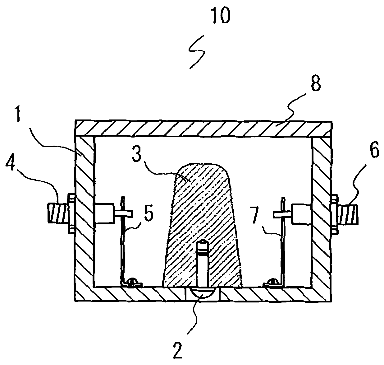
[0023] A semi-coaxial resonator according to an embodiment of the present invention will be described with reference to the drawings. figure 1 It is a side cross-sectional view of the central portion of the semi-coaxial resonator according to the embodiment of the present invention. exist figure 1 The middle and half coaxial resonator 10 includes: a U-shaped housing 1 with a U-shaped cross-section made of metals such as aluminum and copper; ; the input connector 4 arranged on the side of the housing 1; the coupling plate 5 arranged between the core wire part of the input connector 4 and the bottom surface of the housing 1 and used to couple the input electric wave with the resonator 3; The output connector 6 provided on the side wall of the housing 1 facing the side wall provided with the input connector 4; is arranged between the core wire part of the output connector 6 and the bottom surface of the housing 1, and is used for coupling A coupling plate 7 for outputting radio...

no. 2 approach

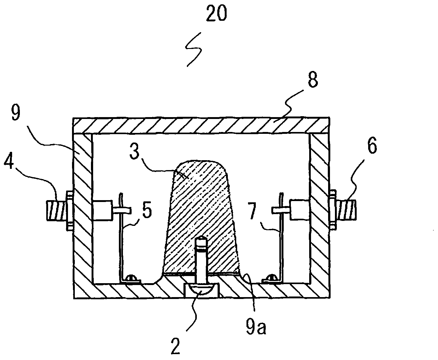
[0030] Next, a semi-coaxial resonator according to another embodiment of the present invention will be described. image 3 It is a side cross-sectional view of the central portion of a semi-coaxial resonator according to another embodiment of the present invention. exist image 3 Among them, the resonator 20 is characterized in that the bottom surface of the case 9 made of metal such as aluminum or copper and having a U-shaped cross section has a pedestal 9a, which is integrally formed with the case 9 and used to set the Resonator 3 shown. In addition, in the figure for the figure 1 The same structural parts are assigned the same reference numerals, and explanations are omitted.

[0031] Figure 4 It is an explanatory diagram of the pedestal 9 a for installing the resonator 3 . In the figure, when looking at the pedestal 9a in a longitudinal cross-sectional shape, the cross-sectional side of the pedestal 9a is in a curved shape erected from the bottom surface of the housing...

no. 3 approach

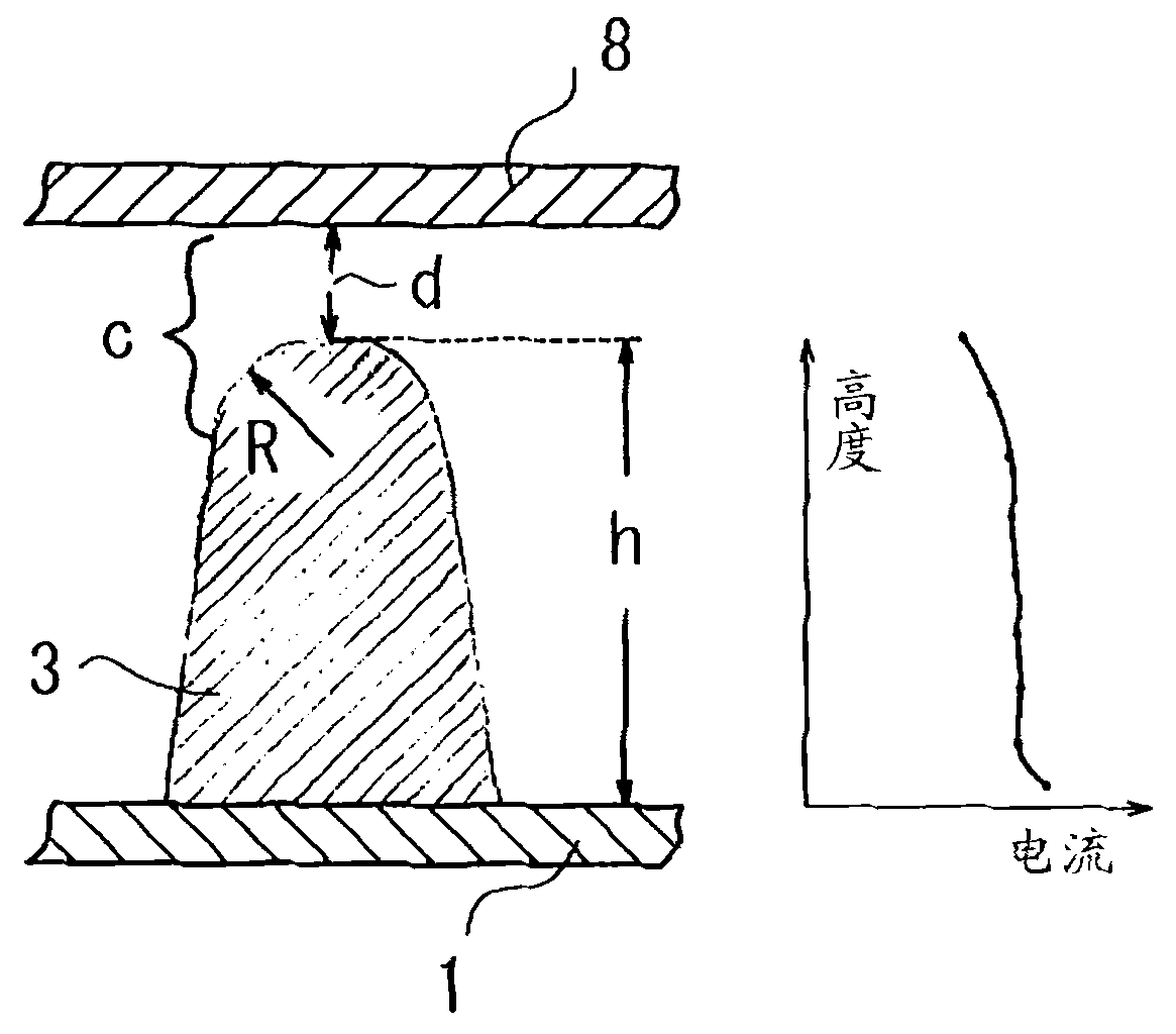
[0035] Next, the suppression of the variation in resonance frequency due to temperature change in the semi-coaxial resonators of Embodiments 1 and 2 will be described. The semi-coaxial resonator of this embodiment is characterized in that, in the semi-coaxial resonators of Embodiments 1 and 2, a material having a coefficient of linear expansion larger than that of the resonator 3 is used as the case 1. , 9 and the material of cover body 8.

[0036] The relationship between the size of the resonator 3 and the resonant frequency is, if,

[0037] ω…angular frequency

[0038] c...top capacitance

[0039] Z O ...the characteristic impedance of the resonator

[0040] θ…The length of the resonator (Electrical Length·Phase Angle Among them, θ<90°)

[0041] d... Gap width

[0042] S...The area of ​​the plane part on the top of the resonator

[0043] ε…Dielectric constant

[0044] So,

[0045] ω=d / (εS Z O Tanθ)

[0046] =1 / (c Z O Tanθ)

[0047] Therefore, if the tip capac...


PUM


Abstract

The present invention provides a semi-coaxial resonator and a filter device, which can restrain resonance frequency variation caused by temperature variation without Q value reduction. A resonator (3) which has a gradually reducing diameter from a base to a top part opposite with a cover (8) and is provided with a sphere at the top is provided at a bottom surface of a housing that is closed by the cover (8). An electric wave is transmitted from an input connector (4) to the resonator (3) through a coupling plate (5). The electric wave excited by the resonator (3) is output from a coupling plate (7) and an output connector (6). The linear expansion coefficients of the housing (1) and the cover (8) are larger than that of the resonator (3). A sheath current of the resonator (3) is same from bottom to top so the Q value does not reduce. Because of the sphere at the top, even when a clearance between the cover (8) and the top of the resonator (3) reduces by temperature variation, the top capacitance does not increase. Therefore the resonance frequency variation caused by temperature variation can be restrained.

Description

technical field [0001] The present invention relates to a semi-coaxial resonator and a filter device used in a filter device of a mobile communication base station device and the like. Background technique [0002] In recent years, it is necessary to ensure high-sensitivity transmission and reception performance and excellent communication performance in mobile communication systems. Therefore, in the base station equipment and the filter equipment of terminal equipment used in this system, it is required to ensure that the signal components are hardly changed. Poor high Q value (quality factor) characteristics and stable pass characteristics even under severe temperature conditions. In addition, the requirements for cheap are also extremely strict. [0003] Dielectric resonators are often used as resonators used in the filter devices of the above-mentioned base station devices. The resonant element (resonator body) of this resonator is made of ceramics. In order to manuf...

Claims


Application Information

Patent Timeline
Patent Type & Authority Applications(China)
IPC IPC(8): H01P7/04H01P1/202
CPCH01P1/202H01P7/04
Inventor 国村真
Owner TAMAGAWA ELECTRONICS
Why Eureka
Try Eureka