
Sealing device of vacuum moving element

A technology of moving parts and sealing devices, applied in the direction of engine sealing, engine components, mechanical equipment, etc., can solve problems such as gas leakage, equipment performance decline, affecting sealing effect, etc., to reduce motion resistance, excellent sealing characteristics, prolong The effect of the service life

Inactive Publication Date: 2011-03-30
FOSHAN JUSHITAI POWDER METALLURGY CO LTD
View PDF9 Cites 16 Cited by
  • Summary
  • Abstract
  • Description
  • Claims
  • Application Information

AI Technical Summary

Problems solved by technology

Since the inner surface of the sealing ring is relatively smooth, for a piston with a large stroke, the long-stroke movement of the piston rod will easily take away the sealing grease attached to it, which will easily lead to the reduction of the sealing grease in the sealing ring, causing The sealing is not strict, causing the cavity to leak air or liquid, which seriously affects its sealing effect; at the same time, when the vacuum moving parts in industrial production equipment or other equipment run continuously for a long time, the sealing device of the above moving parts cannot be fully sealed. Lubrication, the sealing ring or sealing ring wear is large, resulting in a decrease in sealing performance, and at the same time increased movement resistance, resulting in a decrease in equipment performance, so it needs to be replaced frequently, seriously affecting its work efficiency and increasing costs
Therefore, at present, the sealing of moving parts generally encounters a dilemma: that is, if considering the improvement of sealing performance, it is hoped that the sealing ring will be subject to greater pressure and be more tightly combined with the moving parts, but this will increase the resistance of the moving parts and reduce the operation of the equipment. At the same time, because the sealing grease cannot be replenished in real time, the sealing performance drops rapidly
The Chinese invention patent with the application number "200810055727.4" discloses a multiple sealing device, which consists of several parts, including a sealing block with multiple sealing ring placement grooves, a hollow sealing ring with an n-shaped cross section, and a cylindrical working surface There is a groove on it, which leads to the hollow sealing ring. This invention has the characteristics of pressure resistance and small leakage. However, because the device has many gaps and works in a vacuum state, it is more prone to gas internal leakage.
Although the above structures can achieve the sealing effect to a certain extent, they all have defects such as complex structure, large wear, frequent replacement and easy loss of sealing and lubricating materials, and are not suitable for sealing large-scale and large-size moving parts.

Method used


Image

  • Sealing device of vacuum moving element
  • Sealing device of vacuum moving element
  • Sealing device of vacuum moving element

Examples


Embodiment 1

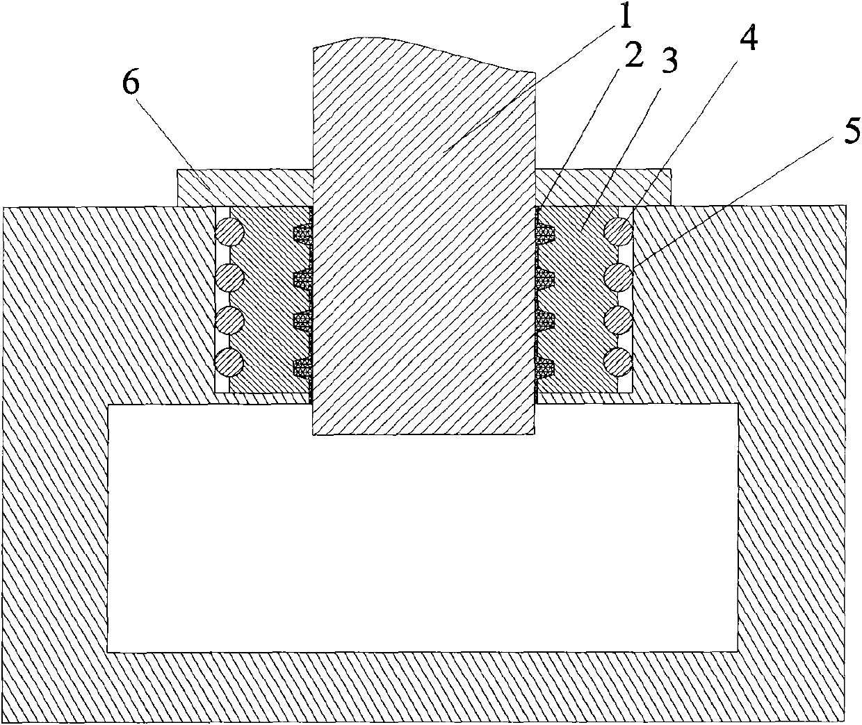
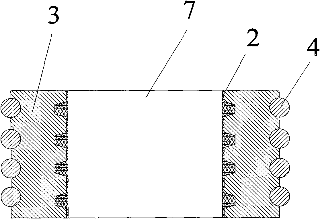
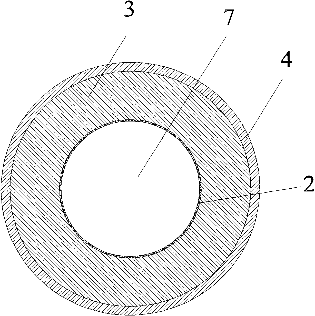
[0040] Figure 1 to Figure 5 Shows the specific structural diagram of this embodiment, such as figure 1 As shown, this vacuum moving part sealing device includes a moving part 1 and a sealing ring 3 matched with it, and the inner hole wall of the inner hole 7 of the sealing ring 3 matching with the moving part 1 is provided with four ring-shaped storage grooves 8. Both the inner hole wall and the storage tank 8 have a sealing grease layer 2; the outer wall of the sealing ring 3 is provided with four outer ring grooves 9, each outer ring groove 9 is embedded with a sealing ring 4, and the sealing ring 4 is in contact with the cavity The sealing inner wall 5 cooperates.

[0041] Such as figure 2 and Figure 4 As shown, the cross-sectional shape of the storage tank 8 is trapezoidal.

[0042] The cross-sectional shape of the outer ring groove 9 is a semicircle.

[0043] Each outer ring groove 9 is embedded with a sealing ring 4 .

[0044] The distance between the peripheral...

Embodiment 2

[0056] Present embodiment except following feature other structures are with embodiment 1: as Figure 6 As shown, the inner hole wall and the surface of the storage tank 8 are also provided with a polytetrafluoroethylene coating 10 .

[0057] The sealing ring 3 is made of perfluororubber, and the sealing ring 4 is made of silicon rubber.

Embodiment 3

[0059] The structure of this embodiment is the same as that of Embodiment 1 except for the following features: the inner hole wall of the inner hole 7 of the sealing ring 3 cooperating with the moving part 1 is provided with seven annular storage grooves 8, the inner hole wall and the storage groove 8 have a sealing grease layer 2; the outer wall of the sealing ring 3 is provided with four outer ring grooves 9, and each outer ring groove 9 is embedded with a sealing ring 4, and the sealing ring 4 cooperates with the cavity sealing inner wall 5.

[0060] Such as Figure 7 As shown, the cross-sectional shape of the storage tank 8 is a rectangle with a side length of 5 mm.

[0061] The cross-sectional shape of the outer ring groove 9 is a semicircle.

[0062] The distance between the peripheral edges of every two adjacent storage grooves is 2mm, and the distance between the peripheral edges of every two adjacent outer ring grooves is also 2mm.

[0063] The cross-sectional shape...


PUM

PropertyMeasurementUnit
Inner diameteraaaaaaaaaa
The inside diameter ofaaaaaaaaaa

Abstract

The invention provides a sealing device of a vacuum moving element, which comprises a moving element and a sealing ring matched with the moving element, wherein the inner hole wall of the sealing ring, matched with the moving element, is provided with a plurality of annular storing slots; the inner hole wall and the storing slots are all provided with sealing grease layers or lubricant layers; the outer wall of the sealing ring is provided with a plurality of outer ring slots; a sealing circle is embedded into each outer ring slot; and the sealing circles are matched with the sealing inner wall of a cavity body. The sealing device has the bidirectional sealing property, in particular the sealing of excellent sealing property in the frequent large-travel reciprocating motion for a long time under the vacuum or high pressure difference conditions; the inner hole wall of the sealing ring is provided with the storing slots capable of storing a certain amount of sealing grease or lubricant to effectively supplement the sealing grease or the lubricant taken way by the motion of the moving element so as to maintain the excellent sealing property at the same time of reducing motion resistance; and the pretightening force is supplied through the deformation of the sealing circle, the sealing circle can supplement the abrasion of the sealing ring, and thus, the service life of the sealing ring is prolonged.

Description

technical field [0001] The invention relates to a sealing device, in particular to a sealing device for vacuum moving parts. Background technique [0002] The function of the sealing device is to prevent liquid leakage or air leakage. It is mainly used in high-pressure fluid sealing, piston sealing, vacuum sealing and other fields. Most of the sealing devices used today are sealing rings. At present, commonly used sealing rings include O-rings, V-rings, etc. Traditional V-rings can only provide one-way sealing performance. Ordinary O-rings can only provide simple sealing. Due to structural reasons, the sealing effect is relatively poor and the service life is short. Especially in the case of sealing sliding parts, it is easy to cause sealing failure due to cracking or the like. [0003] The sealing device is also often used in the sealing of moving parts, such as vacuum pistons, etc. For the sealing of these moving parts, the sealing is generally realized by applying seal...

Claims


Application Information

Patent Timeline
IPC IPC(8): F16J15/18F16J15/20
Inventor 崔明培王家生任山叶志超李立强
Owner FOSHAN JUSHITAI POWDER METALLURGY CO LTD
Learn More