Resistance capacitance (RC) oscillator with low power consumption

A technology of oscillators and inverters, applied in the field of oscillators, can solve the problems of RC oscillator duty cycle performance degradation, duty cycle drop, etc.

Inactive Publication Date: 2011-03-30
SAMSUNG SEMICON CHINA RES & DEV +1
View PDF0 Cites 19 Cited by
  • Summary
  • Abstract
  • Description
  • Claims
  • Application Information

AI Technical Summary

Problems solved by technology

[0030] Second, due to the different parasitic capacitances at the two nodes FEED and FEEDB, the duty cycle performance of the RC oscillator is degraded
[0031] Third, in this RC oscillator, an inverter is inserted between the nodes FEED and FEEDB, then there is an inverter delay between these two signals, which changes the original completely symmetrical circuit, and also makes the occupied Duty down

Method used


Image

  • Resistance capacitance (RC) oscillator with low power consumption
  • Resistance capacitance (RC) oscillator with low power consumption
  • Resistance capacitance (RC) oscillator with low power consumption

Examples


Embodiment Construction

[0038] Hereinafter, embodiments of the present invention will be described in detail with reference to the drawings.

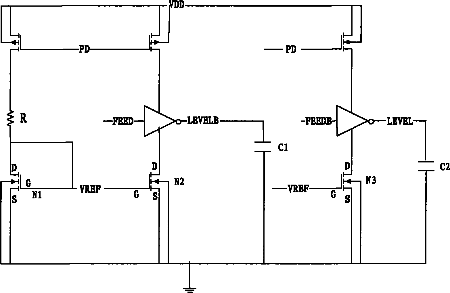
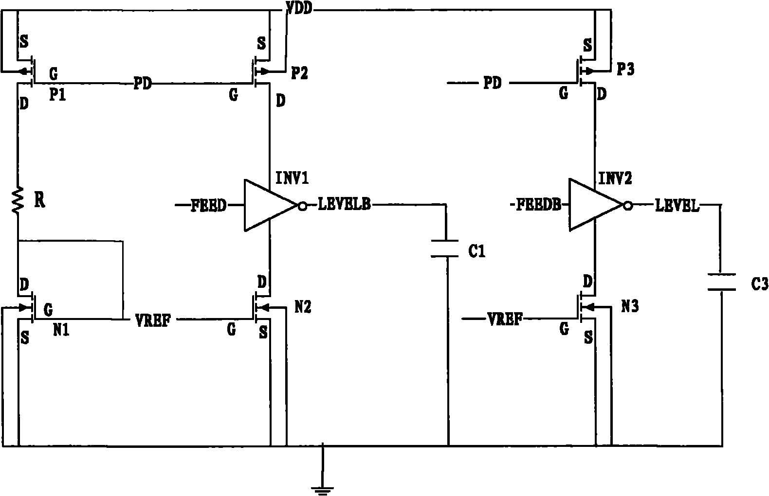
[0039] image 3 and Figure 4 shows a schematic diagram of an RC oscillator according to the invention, Figure 5 show image 3 The internal structure diagram of the inverter in .

[0040] image 3 with existing technology figure 1 are basically the same, except that the feedback to image 3 The node FEED signal in the figure 1 The situation shown in is different.

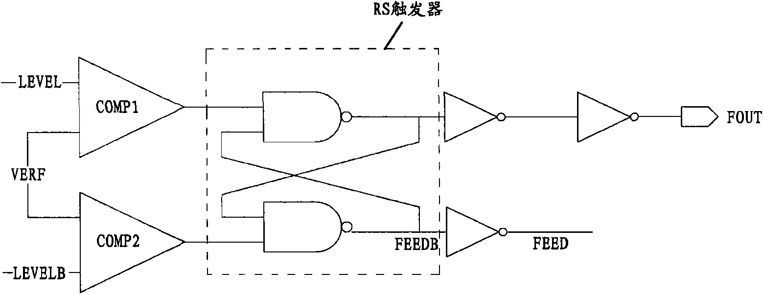
[0041] refer to image 3 and Figure 4 , the RC oscillator according to the present invention includes a bias circuit, an RS flip-flop and some digital logic.

[0042] Specifically, the RC oscillator includes: a bias circuit including a resistor R and a first NMOS transistor N1; a first inverter INV1, a second NMOS transistor N2, and a first capacitor C1; a second inverter INV2, a first Three NMOS transistors N3 and the second capacitor C2; the third inverter INV3 to the sixth inverter I...


PUM


Abstract

The invention provides a resistance capacitance (RC) oscillator with low power consumption, which can generate clock control signals with a duty ratio of which the accuracy is increased required by an internal circuit. The RC oscillator comprises a bias circuit, a first inverter, a second n-channel metal oxide semiconductor (NMOS) transistor, a first capacitor, a second inverter, a third NMOS transistor, a second capacitor, a third inverter, a fourth inverter, a fifth inverter, a sixth inverter, an RS trigger, a nor gate and a fourth NMOS transistor, wherein the bias circuit comprises a resister and a first NMOS transistor; a first input end and a second input end of the RS trigger are respectively connected with a first input end and a second input end of the nor gate; the output end of the nor gate is connected with a grid electrode of the fourth NMOS transistor; a first output end of the RS trigger is connected with a drain electrode of the fourth NMOS transistor; and the source electrode of the fourth NMOS transistor is grounded.

Description

technical field [0001] The invention relates to an oscillator in a CMOS integrated circuit, in particular to an RC oscillator with low power consumption, which can generate a clock control signal with improved duty cycle precision required by an internal circuit. Background technique [0002] Commonly used oscillators are generally divided into three types: RC oscillators (ie, resistance-capacitance oscillators), ring oscillators, and crystal oscillators. The RC oscillator has the advantages of short start-up time, easy frequency adjustment, and easy design and manufacture using common CMOS integrated circuit technology. [0003] figure 1 and figure 2 A schematic diagram of a prior art RC oscillator is shown. [0004] Such as figure 1 and figure 2 As shown, the RC oscillator includes a bias circuit, two comparators COMP1 and COMP2, an RS flip-flop and some digital logic. [0005] The bias circuit in the RC oscillator includes a resistor R and a diode-connected NMOS t...

Claims


Application Information

Patent Timeline
Patent Type & Authority Applications(China)
IPC IPC(8): H03K3/02
Inventor 由玉哲
Owner SAMSUNG SEMICON CHINA RES & DEV
Why Eureka
Try Eureka