Programmable logic circuit

A technology for programming logic and circuits, which is applied in the field of logic circuits, can solve problems that cannot meet the requirements well and have high requirements, and achieve the effect of saving the number of transistors

Active Publication Date: 2011-03-30
BEIJING MXTRONICS CORP +1
View PDF4 Cites 17 Cited by
  • Summary
  • Abstract
  • Description
  • Claims
  • Application Information

AI Technical Summary

Problems solved by technology

However, in many occasions, the requirements for such circuits capable of realizing multiple logic functions are very high, such as low power consumption, small

Method used


Image

  • Programmable logic circuit
  • Programmable logic circuit
  • Programmable logic circuit

Examples


Embodiment Construction

[0028] Such as Figure 6 Shown is a programmable logic circuit 200 proposed by the present invention. The programmable logic circuit 200 can be programmed to realize four logic functions of XOR, AND, XOR, or. The programmable logic circuit 200 includes programmable logic circuit modules 220, 230, and 240, which are composed of ten transistors M1-M10. Through the cooperation of three control signals SELECT1, SELECT2, and SELECT, the two input signals IN1 and IN2 are respectively implemented as described above. Four kinds of logical operations finally get an output signal OUT.

[0029] The programmable logic circuit module 220 implements the NOR function and the AND function, including transistors 201 , 202 , 203 , and 204 . Transistors 201 and 202 are P-channel field effect transistors, transistors 203 and 204 are N-channel field effect transistors, programmable logic circuit module 220 receives input signals IN1 and IN2 through input signal lines 209 and 210, and transmits o...


PUM


Abstract

The invention discloses a programmable logic circuit. The programmable logic circuit comprises 4 P-channel metal oxide semiconductor (PMOS) transistors and 6 N-channel metal oxide semiconductor (NMOS) transistors. Four logical functions, namely AND, OR, XOR and XNOR logics of two input signals, are realized by only using ten transistors and are four basic circuits which are commonly used for establishing systems. The ten transistors are divided into three groups, wherein the first group consists of two NMOS transistors and two PMOS transistors for realizing the logical functions such as AND and XNOR; the second group consists of two NMOS transistors and two PMOS transistors for realizing the logical functions such as OR and XOR; and the third group consists of two NMOS transistors for realizing the logical function of selecting whether to output the first group or the second group finally by using an either-or multiplexer. The circuit structure respectively realizes the circuit structure of the first group and the circuit structure of the second group by ingeniously utilizing the relationships between truth tables of two input AND logics and XNOR logics as well as two input OR logics and XOR logics. The same circuit functions as those of the programmable logic circuit are realized by 26 transistors in a conventional method; however, only 10 transistors are used in the programmable logic circuit.

Description

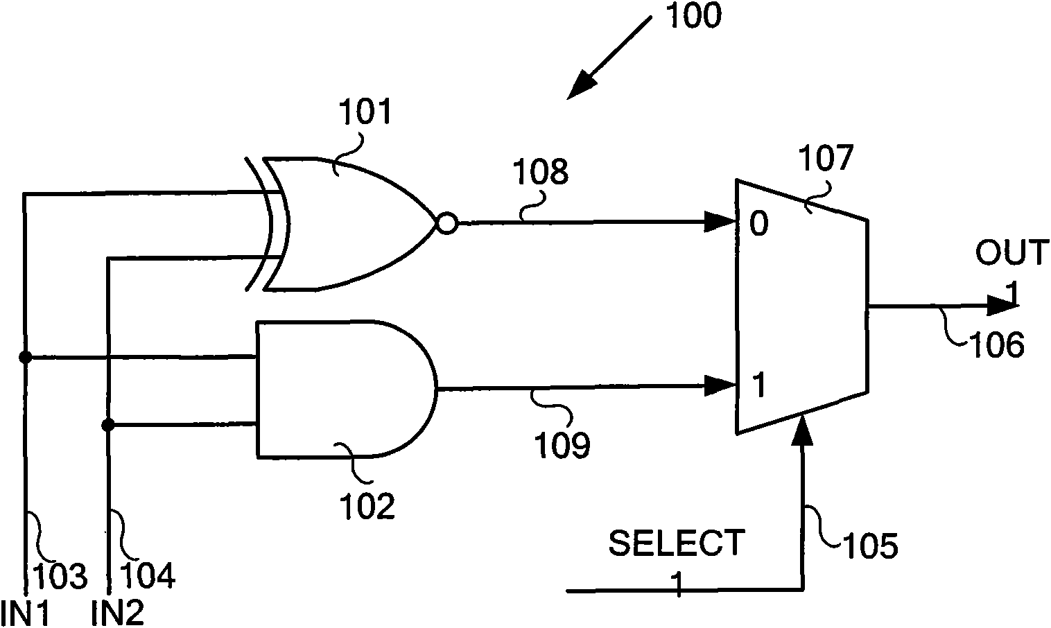
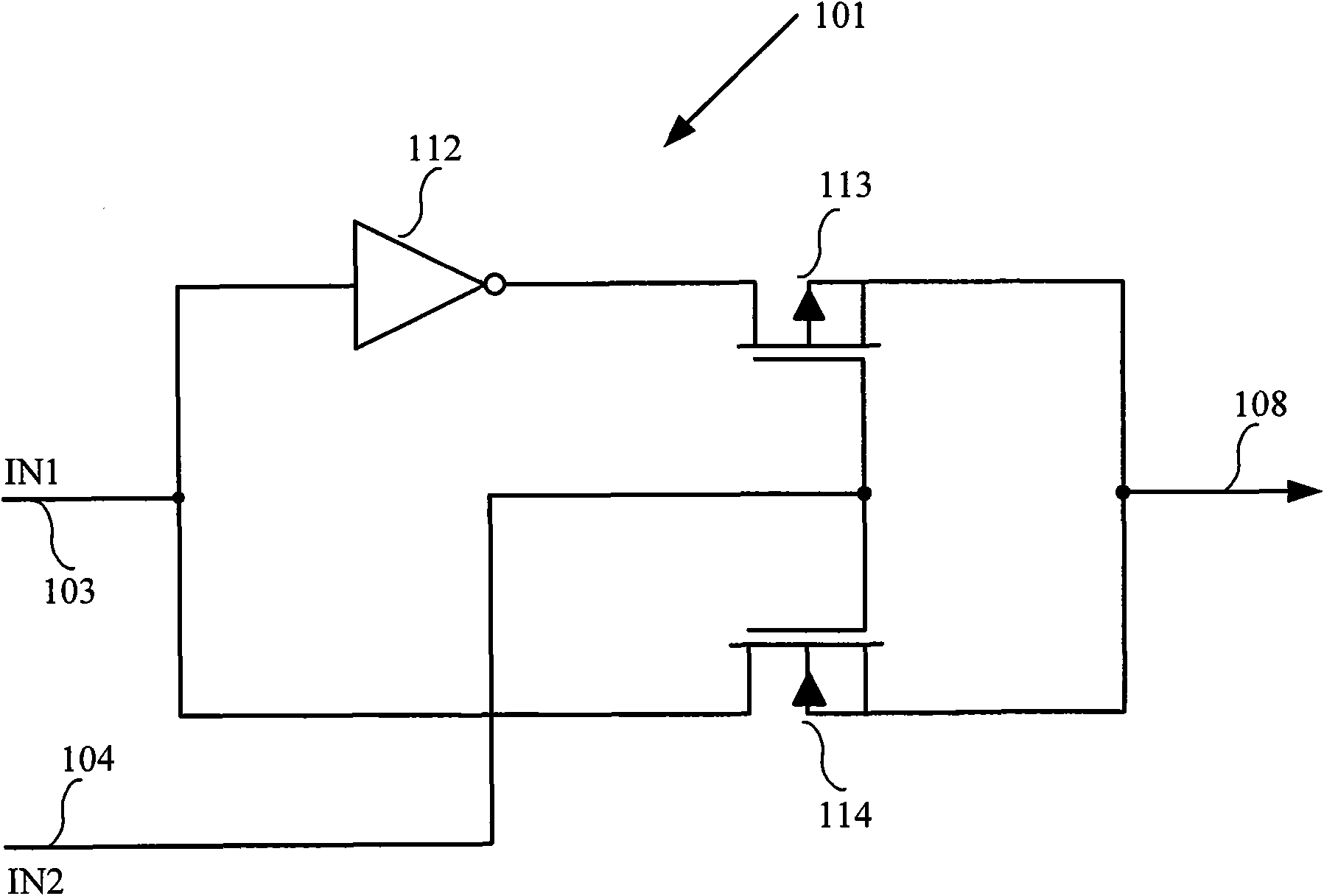
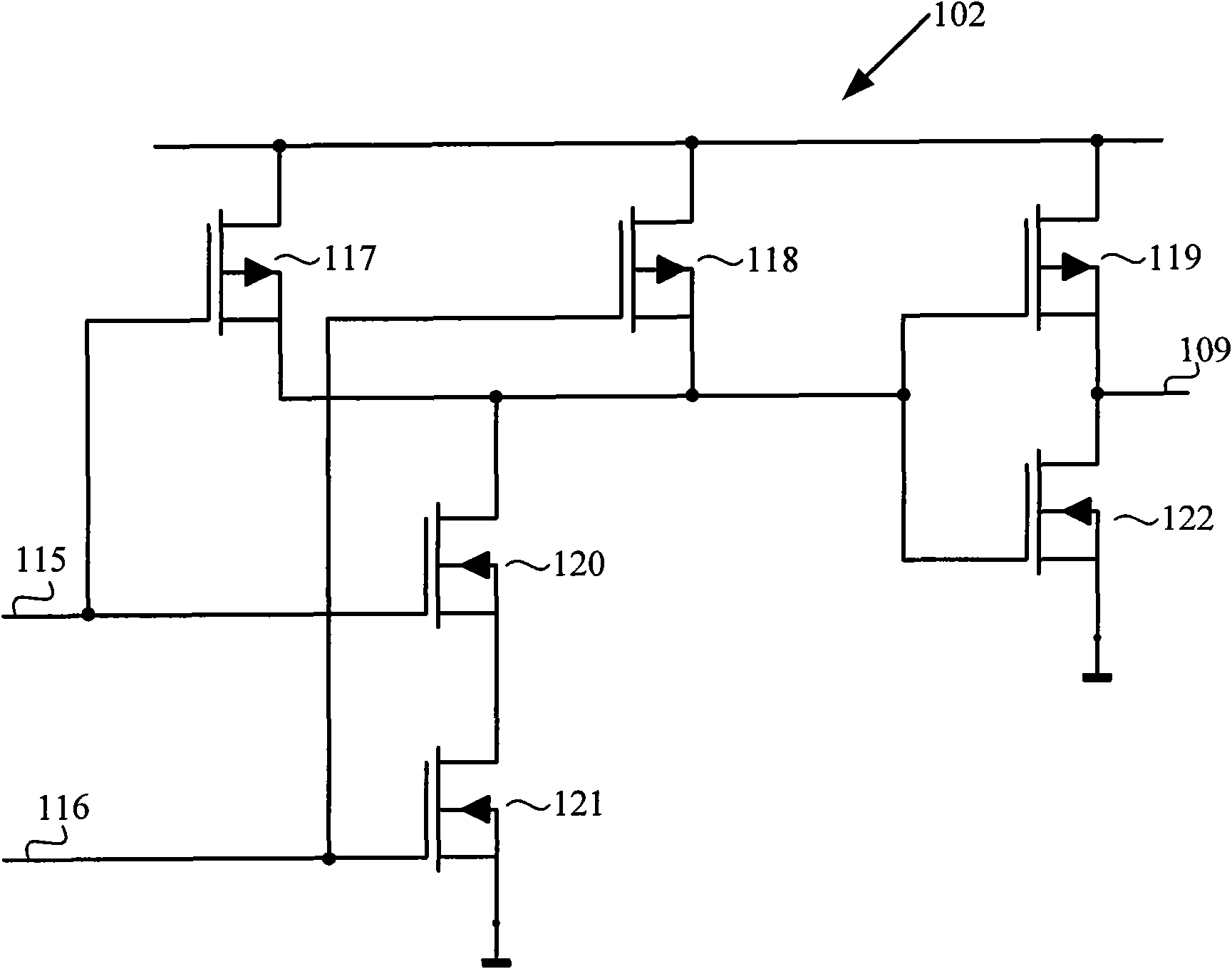
technical field [0001] The invention relates to a programmable logic circuit, which is a logic circuit which realizes four logic functions by only using 10 transistors. Background technique [0002] figure 1 is a schematic diagram of a commonly used logic circuit 100 for realizing the NOR function or the AND function. The logic circuit 100 includes a two-input NOR gate 101 , a two-input AND gate 102 , and a two-to-one multiplexer 107 . The exclusive OR gate 101 is a standard logic gate, which realizes the exclusive OR function. The AND gate 102 is a standard logic gate, which realizes the AND function. Both the NOR gate 101 and the AND gate 102 receive input signals from the input line IN1 103 and the input line IN2 104 , the output of the NOR gate 101 is connected to the line 108 , and the output of the AND gate 102 is connected to the line 109 . [0003] The output signal line 108 of the NOR gate 101 is connected to the “0” input terminal of the multiplexer 107 , and t...

Claims


Application Information

Patent Timeline
IPC IPC(8): H03K19/20
Inventor 王慜刘增荣张彦龙陈雷李学武
Owner BEIJING MXTRONICS CORP
Why Eureka
Try Eureka