Laser cutting method

A laser cutting and cutting head technology, applied in laser welding equipment, welding equipment, metal processing equipment, etc., can solve the problems of rising management costs, low cutting efficiency, high requirements for operating skills, etc., and achieve high positioning accuracy and motion positioning accuracy , Guarantee cutting efficiency and expand the scope of application

Inactive Publication Date: 2011-04-06
HANS LASER TECH IND GRP CO LTD
View PDF2 Cites 14 Cited by
  • Summary
  • Abstract
  • Description
  • Claims
  • Application Information

AI Technical Summary

Problems solved by technology

Manual cutting is a relatively primitive cutting method, which requires high operating skills, and the cutting quality is uncontrollable. The main problems are reflected in the following aspects: poor cutting dimension accuracy, arc and straight line, arc and arc connection It is difficult to guarantee the continuity of parts and the consistency of different parts, the surface is prone to accidental damage, the cutting efficiency is low, and the requirements for operating skills and proficiency are high, etc.
The problems focus on dimensional accuracy, efficiency, appearance and the training of skilled workers, so it is difficult to form a higher level of mass production, which affects the popularization and development of this new technology
[0005] A certain mobile phone screen adopts injection molding manufacturing process. The process of removing the nozzle of injection molded parts involved in this process is currently using a punching process. The executive device of the punching process is mainly a cutter. The main problems of this process are as follows: Aspects: The nozzle is located on the edge of the curve or the nozzle cannot be cut in space. The contact punching process may cause damage to the surface of the part or tearing near the incision of the part. The same cutter cannot be compatible with different types of nozzles, etc.
The problem is that the special-shaped nozzle cannot be cut, which may lead to an increase in the amount of scrap and an increase in the management cost caused by the increase in the number of cutters.

Method used


Image

  • Laser cutting method
  • Laser cutting method
  • Laser cutting method

Examples


Embodiment Construction

[0029] Further description will be made below in conjunction with the preferred embodiment shown in each accompanying drawing.

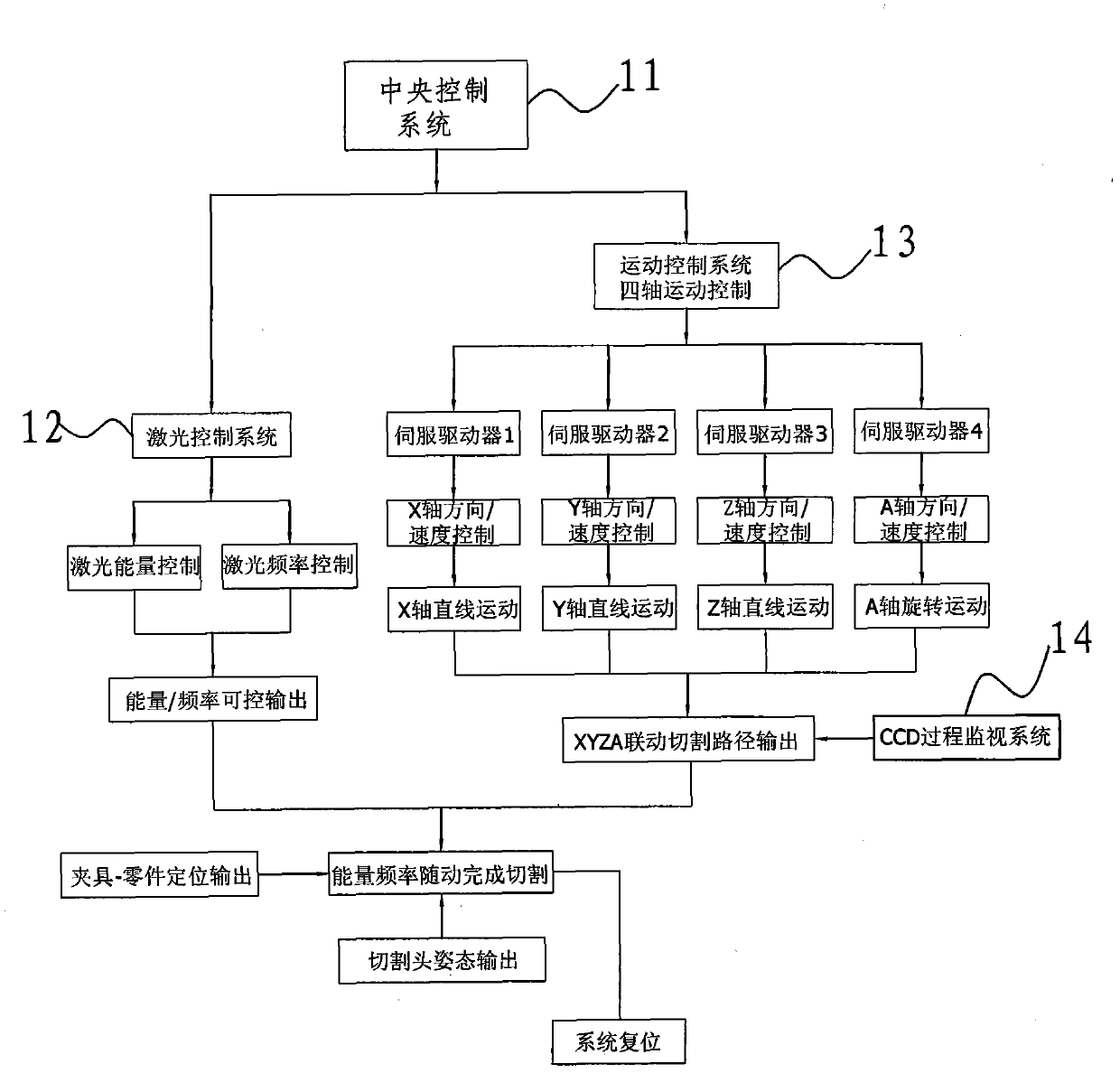
[0030] The present invention relates to a kind of laser cutting method, the implementation of this method needs to mention a kind of system combination, such as figure 1 , the system combination includes: a multi-axis linkage workbench, a laser cutting machine, and a CCD process monitoring system 14, wherein the process of the entire method requires a central control system 11 to adjust and control the motion control system 13 of the cutting path of the workbench, and control the laser cutting machine. The energy and frequency laser control system 12 and the program control software for executing each system; in this embodiment, the laser cutting is a CO2 laser cutting machine.

[0031] like figure 1 In the described embodiment, the multi-axis linkage workbench is an XYZ-A four-axis linkage workbench, and the linear motion speeds in the X, Y, Z, a...


PUM


Abstract

The invention provides a laser cutting method, in particular to a method for removing a water gap of an injection molding and a water gap of a film-covering piece by adopting a cutting path employing teaching programming and related program recording method. The teaching programming method comprises the following steps of: gradually recording the postures and the instant speeds of cutting heads on a curve one by one; associating the data to form continuous cutting motion; and teaching and storing a whole cutting path as a CNC (Computerized Numerical Control) program, wherein regular curves are used for teaching according to the characteristics, and irregular curves are used for teaching by adopting a short line segment fitting method. In the invention, by adopting a mode of controlling the motion of a worktable and the frequency and the energy of laser through program and a working mode of normal cutting, the requirement for operators can be lowered, meanwhile, the processing constancy and the joining continuity between a notch and an arc are ensured, the cutting quality is improved and the application range of laser cutting is further enlarged.

Description

【Technical field】 [0001] The invention relates to a laser cutting method for removing nozzles of injection molded parts and non-metallic film-coated parts, especially a laser normal cutting method for irregularly shaped nozzles of injection molded parts and non-metallic film-coated parts. 【Background technique】 [0002] The part formed by the flow channel after the injection molding part is solidified is called the nozzle; the part with a non-metallic film on the surface is called a film-coated part, and the non-metallic flash on the edge of the film-coated part is also called a nozzle here. The method of using laser focus to generate energy to cut objects is called laser cutting process. The process method we want to disclose is how to use laser cutting method to remove the nozzle of injection molded parts and the flash of film-coated parts. [0003] According to the shape of the nozzle edge of the coating part, it can be defined as a plane nozzle and a space nozzle. The n...

Claims


Application Information

Patent Timeline
Patent Type & Authority Applications(China)
IPC IPC(8): B23K26/36B23K26/02B23K26/38
Inventor 张洪鑫潘红日高云峰
Owner HANS LASER TECH IND GRP CO LTD
Why Eureka
Try Eureka