Magnetic flux-switching generator

A magnetic flux switching and generator technology, which is applied to the static parts of the magnetic circuit, the rotating parts of the magnetic circuit, the shape/style/structure of the magnetic circuit, etc. Winding utilization rate and other issues, to achieve the effect of compact structure, small moment of inertia, and less processing equipment

Active Publication Date: 2011-04-06
SOUTHEAST UNIV
View PDF5 Cites 21 Cited by
  • Summary
  • Abstract
  • Description
  • Claims
  • Application Information

AI Technical Summary

Problems solved by technology

[0005] (1) The generator outputs a three-phase alternating current with a mutual difference of 120 degrees. Generally, three-phase rectification is required to obtain a direct current voltage, resulting in high cost of the rectification part of the system, which is not suitable for low-cost applications;
[0006] (2) The cogging with the number of permanent magnets (that is, the number of stator poles) and the number of rotor teeth are not equal, resulting in two (for six-slot / five-pole structure) or four coils (for twelve-slot / There is a distribution factor between the ten-pole or fourteen-pole structure), so that there is a phase difference between the induced potentials generated by each coil, so that the combined induced potential amplitude is smaller than the algebraic sum of the induced potential amplitudes of each coil, which reduces the winding. Utilization

Method used


Image

  • Magnetic flux-switching generator
  • Magnetic flux-switching generator
  • Magnetic flux-switching generator

Examples


Embodiment Construction

[0022] In order to make the technical means, creative features, goals and effects achieved by the present invention easy to understand, the present invention will be further described below in conjunction with specific embodiments.

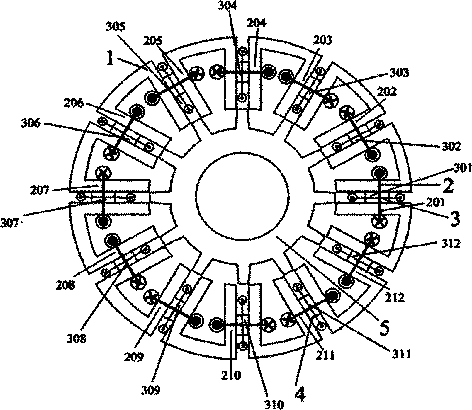
[0023] see figure 1 , the present invention includes a stator 1 and a rotor 5, the stator 1 and the rotor 5 are made of silicon steel punched sheets, the rotor 5 is located inside the stator 1, and the rotor 5 can also be made into an outer rotor 5 structure, the stator 1 and the rotor 5 All are salient pole structures; the stator 1 includes twelve U-shaped magnetic conducting cores and twelve rectangular magnetic conducting bridges 4, two adjacent U-shaped magnetic conducting cores are connected as a whole through a rectangular magnetic conducting bridge 4, and the U-shaped The magnetic core is made of the same material as the rectangular magnetic bridge 4 , and the stator 1 is respectively provided with a single-phase concentrated armature windi...


PUM


Abstract

The invention discloses a magnetic flux-switching generator, which comprises a stator, a rotor, a magnet exciting coil and an armature coil, wherein the number of the poles of the rotor is equal to the number of the slots of the stator; the two circle edges of the armature coil are positioned in two adjacent slots of two adjacent stator gears; winding coils are connected end to end in series in turn to form single-phase centralized armature windings; and the magnet exciting coil is vertical to the armature coil. In the invention, the single-phase centralized armature windings and a permanent magnet or/and single-phase centralized magnet exciting windings are adopted in the stator part, the rotor has straight or slant slots and the number of the poles of the rotor is equal to that of the slots of the stator; and thus, the generator retains the structural advantages of compactness, simplicity, high robustness and suitability for high-speed rotation of the conventional magnetic flux-switching generator and can be directly used as a single-phase alternating current power supply due to the same phase of the electrodynamic potentials generated by the coils, and the cost of the generator is low.

Description

technical field [0001] The invention relates to a generator, in particular to a magnetic flux switching generator, which belongs to the technical field of motor manufacturing. Background technique [0002] The current single-phase or three-phase generators adopt a structure in which the two sets of windings of the excitation and the armature are placed separately, including a rotating excitation electric excitation structure in which the rotor places the field winding / the stator places the armature winding, and the rotor places the permanent magnet / stator. Rotating excitation permanent magnet structure with armature winding, rotating armature electric excitation structure with excitation winding on stator / armature winding on rotor, rotating armature permanent magnet structure with permanent magnet on stator / armature winding on rotor. The above four structures all require brushes and / or commutators, which reduces the reliability of the system and requires maintenance. [000...

Claims


Application Information

Patent Timeline
Patent Type & Authority Applications(China)
IPC IPC(8): H02K1/22H02K1/24H02K1/14H02K1/16H02K3/28
Inventor 花为吴中泽程明
Owner SOUTHEAST UNIV
Why Eureka
Try Eureka