Paratactic structure hybrid excitation synchronous machine (HESM) and alternating current excitation control system thereof

A hybrid excitation synchronous, AC excitation technology, applied in the direction of motor generator control, control system, vector control system, etc., can solve the problems of not very ideal sinusoidal output voltage, multi-electric excitation magnetomotive force, poor environmental adaptability, etc. Achieve the effects of increasing reliability and environmental adaptability, less magnetomotive force, and high electric excitation efficiency

Inactive Publication Date: 2011-04-06
NORTH CHINA ELECTRIC POWER UNIV (BAODING)
View PDF3 Cites 28 Cited by
  • Summary
  • Abstract
  • Description
  • Claims
  • Application Information

AI Technical Summary

Problems solved by technology

The first type of scheme is similar to the traditional electric excitation generator, the DC excitation current is introduced into the excitation winding on the rotor through brushes and slip rings, and the electric excitation field is rotated by the rotation of the rotor, such as the invention patent No. ZL.200310106347.6 Hybrid excitation synchronous motor, this scheme reduces the reliability and environmental adaptability of the motor due to the existence of brushes and slip rings
[0004] The second type of scheme is a hybrid excitation motor with a double salient pole structure. The DC current flowing through the excitation winding on the motor stator generates a magnetomotive force with a fixed position. The change of the magnetic circuit reluctance when the rotor rotates makes the stator flux change, so that ...

Method used


Image

  • Paratactic structure hybrid excitation synchronous machine (HESM) and alternating current excitation control system thereof
  • Paratactic structure hybrid excitation synchronous machine (HESM) and alternating current excitation control system thereof
  • Paratactic structure hybrid excitation synchronous machine (HESM) and alternating current excitation control system thereof

Examples


Embodiment 1

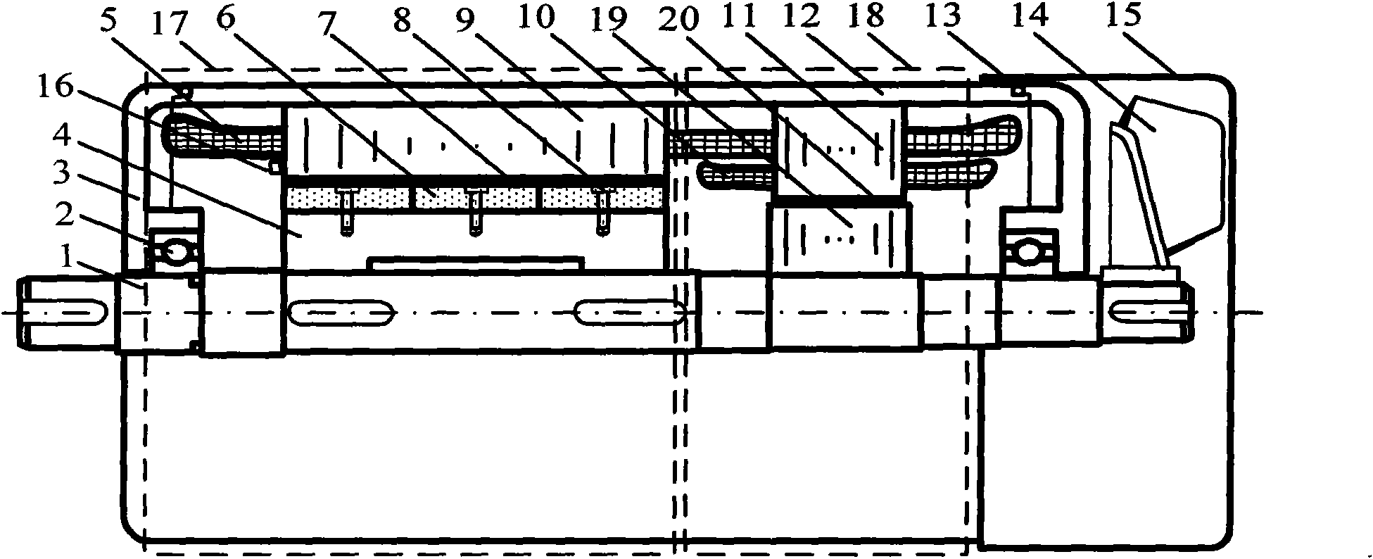
[0044] Depend on figure 1 It can be seen that the parallel structure brushless hybrid excitation synchronous generator is composed of two parts: the permanent magnet part 17 on the left and the electric excitation generator part 18 on the right. The stator iron core 9 of the permanent magnet part and the stator core 11 of the electric excitation part have the same number of slots, which is 36 slots in this embodiment, and the stator slots of the electric excitation part are deeper than those of the permanent magnet part to accommodate the three-phase armature winding 5 and The three-phase excitation winding 10 is the standard; therefore, the diameter of the electric excitation rotor core 19 is smaller than that of the permanent magnet rotor core 4 . The two stators share a set of three-phase armature windings 5, the three-phase armature windings 5 ​​adopt single-layer distributed windings, the number of slots per pole and phase is 3, and the pitch of the windings is 9. It is a...

Embodiment 2

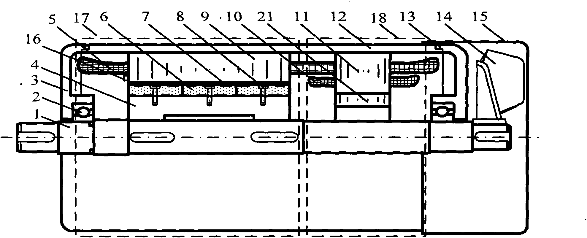
[0073] figure 2 Shown is an axial cross-sectional schematic diagram of a parallel structure hybrid excitation generator with no electric excitation rotor. its overall structure and figure 1 The axial cross-sectional schematic diagram of the parallel structure hybrid excitation synchronous generator shown is the same; its permanent magnet steel has been designed with the pole arc width to reduce the harmonic component in the permanent magnet excitation electromotive force. Add a magnetically permeable ring 21 to the inner circle of the stator core 11 of the electric excitation part. The magnetically permeable ring 21 serves as an inner yoke to provide a path for the electric excitation magnetic field and the armature current magnetic field. In order to reduce the rotating magnetic field of the electric excitation part The eddy current loss is generated on the circular ring 21, and the magnetic permeable ring 21 is formed by laminating circular silicon steel sheets. There is ...

Embodiment 3

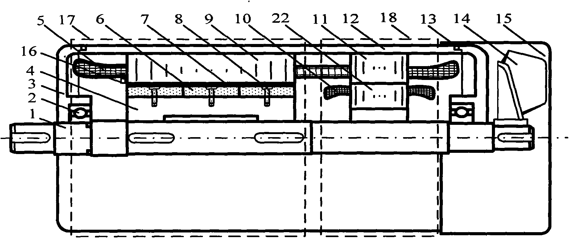
[0076] image 3 The schematic diagram of the axial section of the parallel structure hybrid excitation synchronous generator with double stators in the electric excitation part is shown, and its overall structure and figure 1 The schematic diagram of the axial section of the parallel structure hybrid excitation synchronous generator shown is the same; only the length of the iron core is different, and the two parts of the stator share a set of three-phase armature winding 5, and the three-phase armature winding 5 adopts double-layer short-distance distribution windings, and the stator The number of core slots is 36, the number of slots per pole and phase is 3, and the winding pitch is 7 to weaken the harmonic content of the induced electromotive force in the armature winding. The permanent magnet rotor has 4 poles and adopts a surface magnetic steel structure. The permanent magnet steel 6 is designed for the pole arc width, and the material of the permanent magnet rotor core 4...


PUM


Abstract

The invention discloses a paratactic structure hybrid excitation synchronous machine (HESM) and an alternating current excitation control system thereof, belonging to the technical field of synchronous machine alternating current generation. The permanent magnet part and the electromagnetic part of the HESM are arranged in the same closure in parallel along the axial direction, the stator cores of the permanent part and the electromagnetic part are mutually independent, jointly share one stator armature winding and have the same number of tooth sockets, permanent magnet induced electromotive force and electromagnetic induced electromotive force are superposed in the armature winding, and the purpose of improving the induced electromotive force waveform can be achieved by designing the armature winding distribution mode, the excitation winding distribution mode and the permanent magnet rotor pole shape as well as controlling the exciting current. The magnitude and phase of the electromagnetic induced electromotive force in the armature winding can be adjusted by vector control to enable the alternating current exciting current to only have a direct axis component, thus adjusting the magnitude of the total output voltage of a machine, stabilizing the output voltage of the machine, and realizing constant voltage output in a wide revolving speed range and a large load range.

Description

technical field [0001] The invention belongs to the technical field of synchronous motor AC power generation. It particularly relates to a parallel structure hybrid excitation synchronous generator and its AC excitation control system. Background technique [0002] The permanent magnet synchronous motor has the advantages of high reliability, high efficiency and small size, and has many advantages over the traditional electric excitation synchronous motor. However, since the rotor of the permanent magnet motor is excited by permanent magnet steel, it is difficult to adjust the air gap magnetic field. It operates as a generator. When the temperature rises, the permanent magnet steel produces reversible demagnetization, which reduces the output voltage of the generator. In addition, when the generator When the load changes, especially when the inductive load increases, the output voltage decreases further. Usually the voltage change rate of the permanent magnet generator is ...

Claims


Application Information

Patent Timeline
IPC IPC(8): H02K16/00H02K1/27H02K3/04H02P9/14H02P21/14H02P21/00
Inventor 刘明基于斌李祥永
Owner NORTH CHINA ELECTRIC POWER UNIV (BAODING)
Why Eureka
Try Eureka