Preparation device of ferron used for water treatment and application method thereof
A preparation device and water treatment technology, applied in the field of water treatment, can solve the problems of expensive use, low efficiency, unsuitable for advanced treatment, etc., and achieve the effect of reducing economic costs and saving power and energy.
- Summary
- Abstract
- Description
- Claims
- Application Information
AI Technical Summary
Problems solved by technology
Method used
Image
Examples
Embodiment 1
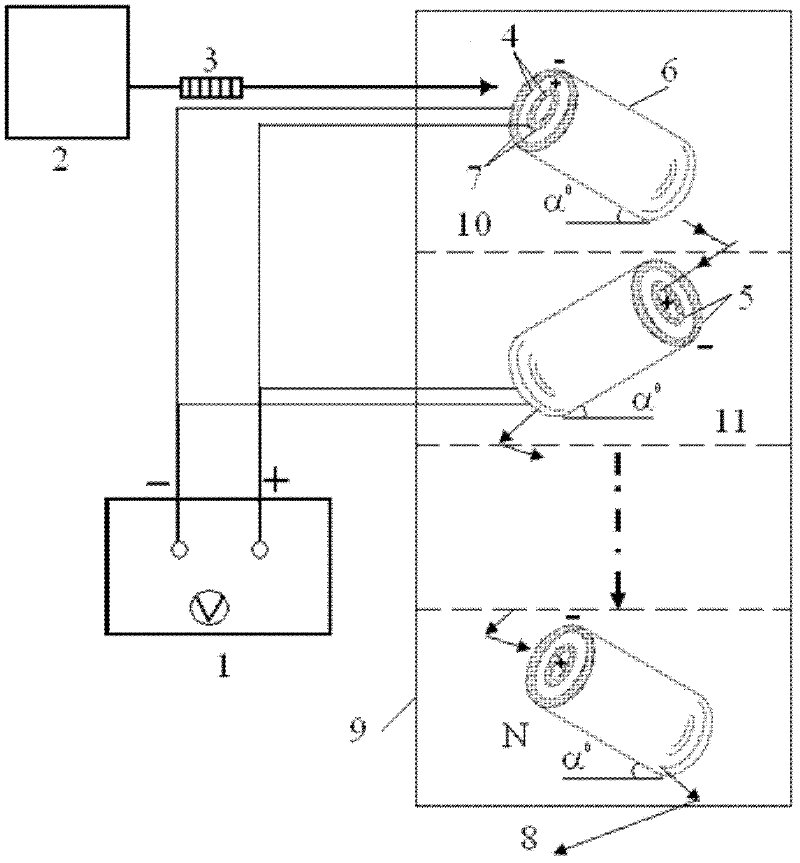
[0048] Such as figure 1 As shown, the preparation device for iron reagent for water treatment is mainly composed of a power supply 1, a tubular iron source generator device 9, and an electrolyte liquid storage tank 2. In this embodiment, a DC power supply capable of periodically changing the polarity of positive and negative polarities is used, and the switching period is 10s. Wherein, the tubular iron source generator device 9 is composed of three tubular generating units 10 connected in series, each generator unit is 300 mm long, and each tubular generating unit 10 is placed at an angle of 30° with the horizontal direction.
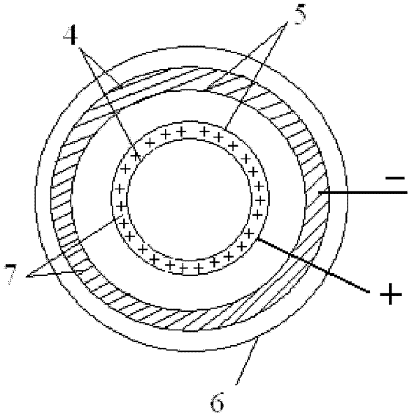
[0049] The tubular porous support material layer is made of taper-like raw cast iron. In this embodiment, only two layers of tubular support material nested inside and outside are used as the anode layer and the cathode layer (that is, the thickness of the iron filings layer is 0, and the mesh-like permeable material layer 5 is not provided), wherein t...
Embodiment 2
[0053] Implementation was carried out in the same manner as in Example 1. The difference is that both the anode layer and the cathode layer include a tubular porous support material layer, an iron filings layer and a mesh-like permeable material. Wherein, the anode layer is located inside the cathode layer. The specific structure of the anode layer is as follows: a layer of iron filings is attached outside the tubular porous support material layer with a thickness of 2 mm and an outer diameter of 60 mm and a mesh number of 100. The thickness of the iron filings layer is 10 mm. A stainless steel mesh (200 mesh) is overlapped with the obtained permeable material layer 5 . The specific structure of the cathode layer is: a layer of iron filings is attached to a tubular support material layer with a thickness of 2 mm and an outer diameter of 100 mm. The thickness of the iron filings layer is 10 mm, and the iron filing layer is covered by a stainless steel mesh (200 mesh) with a th...
Embodiment 3
[0058] Implementation was carried out in the same manner as in Example 2. The difference is that the tubular iron source generator device 9 is composed of a single tubular generating unit 10, and the length of the generator unit is 1000mm. The iron filings layer thickness of each electrode is 5mm. The permeable material is polytetrafluoroethylene mesh (100 mesh) with a thickness of 0.5 mm. A solar battery with equipment for changing the positive and negative polarities is connected between the anode and the cathode, the conversion period is 20s, and the current density is 10mA / cm 2 . The electrolyte is an aqueous mixture of sodium acetate and acetic acid with a concentration of 0.01mol / L, pH=4.5, and the electrolyte passes through the iron source generator at a flow rate of 50ml / min to obtain an iron reagent with a total iron concentration of 2g / L.
PUM
| Property | Measurement | Unit |
|---|---|---|
| length | aaaaa | aaaaa |
| thickness | aaaaa | aaaaa |
| thickness | aaaaa | aaaaa |
Abstract
Description
Claims
Application Information
 - R&D
- Intellectual Property
- Life Sciences
- Materials
- Tech Scout
- Unparalleled Data Quality
- Higher Quality Content
- 60% Fewer Hallucinations
Browse by: Latest US Patents, China's latest patents, Technical Efficacy Thesaurus, Application Domain, Technology Topic, Popular Technical Reports.
© 2025 PatSnap. All rights reserved.Legal|Privacy policy|Modern Slavery Act Transparency Statement|Sitemap|About US| Contact US: help@patsnap.com


