Photoelectronic device for distributed optical fiber temperature sensor

A temperature sensor, distributed optical fiber technology, applied in the direction of thermometers, measuring devices, coupling of optical waveguides, etc., can solve the problems of insufficient isolation, distorted temperature curve, and isolation is difficult to exceed 40dB, etc., to improve the temperature resolution. Effect

Inactive Publication Date: 2011-04-13
KINGSHORE NEW RESOURCES ELECTRIC JIANGSU
View PDF5 Cites 9 Cited by
  • Summary
  • Abstract
  • Description
  • Claims
  • Application Information

AI Technical Summary

Problems solved by technology

First of all, this wavelength division multiplexing device uses a 1X3 bidirectional coupler, which will introduce an additional loss of about 9.5dB (10log(1 / 9)=9.5dB), which greatly weakens the available anti-Stokes light and Stokes light intensity; Secondly, the isolation of the device is difficult to exceed 40dB, the reason is the same as above
[0007] If the above-mentioned conventional wavelength division multiplexing device is used in a distributed optical fiber temperature sensor, due to insufficient isolation, it will cause mutual crosstalk between anti-Stokes light and Stokes light, and interference of Rayleigh scattered light. It is difficult to obtain accurate temperature information and high resolution. In severe cases, the temperature curve may even be distorted and the system may not work properly.

Method used


Image

  • Photoelectronic device for distributed optical fiber temperature sensor
  • Photoelectronic device for distributed optical fiber temperature sensor
  • Photoelectronic device for distributed optical fiber temperature sensor

Examples


Embodiment Construction

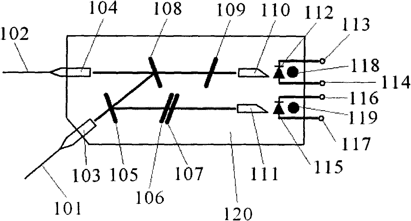
[0032]The photoelectric device for distributed optical fiber temperature sensor of the present invention will be further described in detail below in conjunction with the accompanying drawings and specific embodiments, and this description does not limit the scope of protection of the present invention.

[0033] Such as figure 1 As shown, the photoelectric device used in the present embodiment for the distributed optical fiber temperature sensor consists of collimator pigtails 101, 102, collimators 103, 104, wavelength division multiplexing filter 105 of laser wavelength, Stokes wavelength Bandpass filters 106, 107, multiplexing filter 108 for anti-Stokes wavelength, bandpass filter 109 for anti-Stokes wavelength, self-focusing lens 110, 111, avalanche photodiode (APD) 112, 115 , APD reverse voltage input terminals 113, 116, anti-Stokes electrical signal output terminal 114, Stokes electrical signal output terminal 117, temperature probes 118, 119, device housing 120 and othe...


PUM


Abstract

The invention relates to a photoelectronic device for a distributed optical fiber temperature sensor, which belongs to the technical field of optical fiber sensing. The device comprises a first collimator tail optical fiber and a second collimator tail optical fiber. Wavelength division multiplexing filters are arranged on transmission light paths of a first collimator and a second collimator respectively. Band pass filters are arranged on light paths of the two wavelength division multiplexing filters respectively. A first self-focusing lens and a second self-focusing lens are arranged on the transmission light paths of the two band pass filters. A first avalanche photodiode, a second avalanche photodiode and temperature probes are arranged at the focuses of the two self-focusing lenses respectively. The distributed optical fiber temperature sensor utilizing the photoelectronic device can conveniently acquire accurate temperature information, and improves the temperature resolution of a system.

Description

technical field [0001] The invention relates to a photoelectric device, in particular to a photoelectric device used for a distributed optical fiber temperature sensor, and belongs to the technical field of optical fiber sensing. Background technique [0002] Since J.P.Dakin and others first successfully realized the distributed temperature measurement technology based on Raman scattering in 1985, people have carried out extensive research on various technologies for realizing distributed optical fiber temperature sensing. Sensing technology has been the most widely used in practice. Compared with traditional sensors, distributed optical fiber temperature sensors have many excellent advantages: using optical fiber itself as the sensing medium, temperature information of thousands of points distributed along the optical fiber can be obtained in one measurement, which realizes continuous distributed measurement and reduces the Measurement uncertainty; long measurement distanc...

Claims


Application Information

Patent Timeline
Patent Type & Authority Applications(China)
IPC IPC(8): G01K11/32G02B6/42G01K11/324
Inventor 周金龙朱冬宏田群
Owner KINGSHORE NEW RESOURCES ELECTRIC JIANGSU
Why Eureka
Try Eureka