Broadband high-performance dual-polarization radiation unit and antenna

A radiating element, high-performance technology, applied in the combination of antenna elements with different polarization directions, the structure of radiating elements, antennas, etc., can solve the problem that the impedance pattern performance of high-frequency vibrators is greatly affected, the standing wave and radiation characteristics of high-frequency elements Influence, unfavorable reliability of the processing vibrator, etc., to achieve the effect of improving cross-polarization performance indicators, simple and reasonable structure, and reducing influence

Active Publication Date: 2011-04-13
TONGYU COMM INC
View PDF6 Cites 57 Cited by
  • Summary
  • Abstract
  • Description
  • Claims
  • Application Information

AI Technical Summary

Problems solved by technology

However, the vibrator described in this patent has the following disadvantages in multi-frequency applications: (1) Since the unit arm of the vibrator is linear, this will make the entire vibrator face larger, so that the nested two The high-frequency vibrator between the low-frequency vibrators has a greater impact; (2) Since the balancer structure of the radiation unit in this patent is linear, the distance between the low-frequency vibrator and the high-frequency vibrator will be closer, and the high-frequency vibrator Impedance and pattern performance are greatly affected by low-frequency oscillators
[0004] Although the patent CN 201134512Y has improved the design of the previous patent US 6333720B1, it still has the following disadvantages: (1) The

Method used


Image

  • Broadband high-performance dual-polarization radiation unit and antenna
  • Broadband high-performance dual-polarization radiation unit and antenna
  • Broadband high-performance dual-polarization radiation unit and antenna

Examples


Embodiment Construction

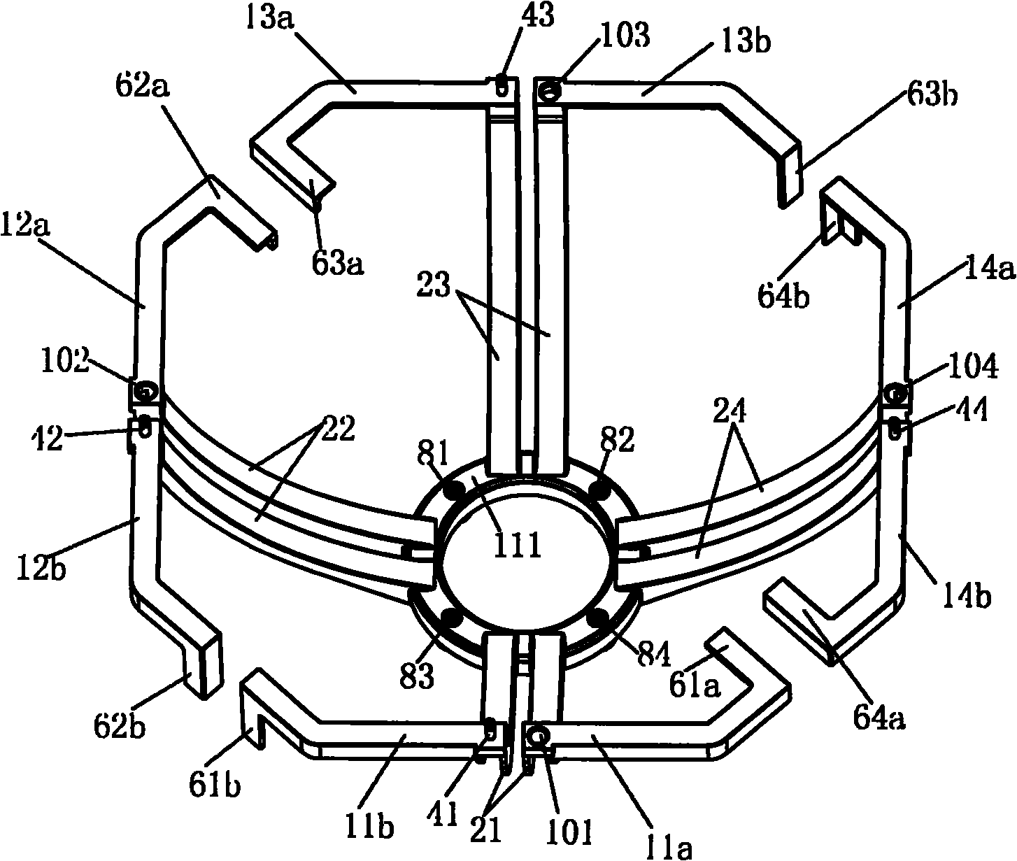
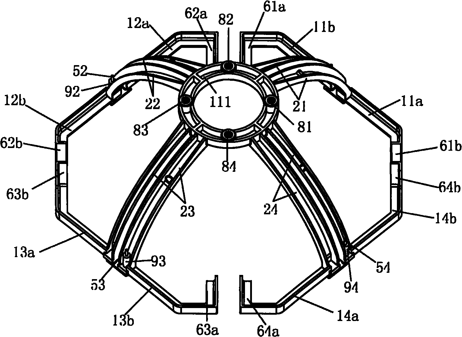
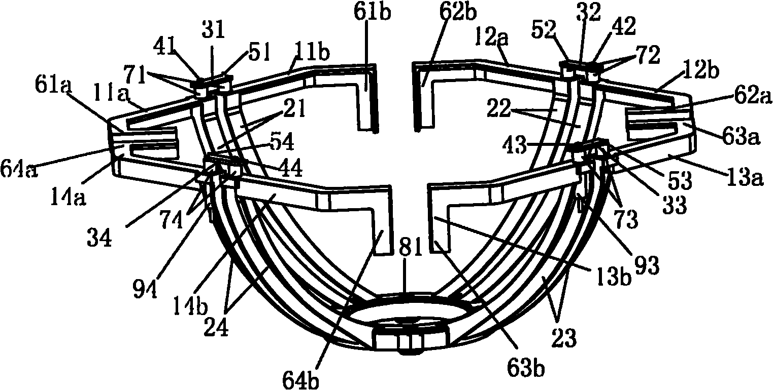
[0026] refer to figure 1 , figure 2 and image 3 , a broadband high-performance dual-polarization radiating unit, including two pairs of polarized orthogonal dipoles, a balancer for balanced feeding of each dipole, and each dipole includes one end symmetrically fixed on a balanced Two unit arms on the balancer, the other end of the unit arm is provided with a loading line, characterized in that each dipole is an asymmetric broken line with respect to the balancer, wherein the loading line at the end of one unit arm Bend inward, the load line at the end of the other element arm bends downward.

[0027] Specifically, the broadband high-performance dual-polarization transmitting unit and antenna described in the present invention include 8 unit arms shown in 11a, 11b, 12a, 12b, 13a, 13b, 14a, 14b, wherein unit arm 11a and unit arm One end of 11b is connected to the balancer 21, and the loading line 61a and the loading line 61b connected to the other end together form a dipole...


PUM


Abstract

The invention discloses a broadband high-performance dual-polarization radiation unit, comprising two pairs of orthogonal polarization dipoles, and a balancer for carrying out balanced feeding on each dipole, wherein each dipole comprises two unit arms one ends of which are symmetrically and fixedly arranged on the balancer, and the other end of each unit arm is provided with a loading wire; and each dipole is in a shape of an unsymmetrical broken line relative to the balancer, wherein the loading wire at the tail end of one unit arm is bent inwards and the loading wire at the tail end of theother unit arm is bent downwards. The loading wire of the dipole in the invention is designed by the combined mode of inward bending and downward bending so as to enable the inwards bent loading wireto be far away from a high-frequency vibrator which is embedded between two low-frequency vibrators to reduce the effect on the high-frequency vibrator; and the downwards bent loading wire excellently compensate the asymmetry of the polarization so as to improve the orthogonal polarization performance index greatly. In addition, the structure design of the invention has greater advantage in cost and reliability.

Description

technical field [0001] The invention relates to the field of mobile communication base station antennas, in particular to a broadband high-performance dual-polarization radiation unit and an antenna. Background technique [0002] At present, under the coexistence of 2G and 3G networks, there are more and more demands for multi-band antennas compatible with 2G and 3G networks, and with the development of communication technology, the performance indicators of multi-band antennas are also getting higher and higher. requirements. [0003] In view of the above development trend, it is more common in the market to use two pairs of dipoles to be distributed orthogonally to form a square or circular antenna design scheme, such as the antenna design scheme disclosed in the patent US 6333720B1, the vibrator described in this patent Two pairs of dipoles are placed orthogonally, the vibrator arm is linear, and the entire vibrator cross-section is a square structure. The vibrator can b...

Claims


Application Information

Patent Timeline
IPC IPC(8): H01Q1/36H01Q5/01H01Q19/10H01Q21/26H01Q5/10
CPCH01Q9/16H01Q21/30H01Q19/106H01Q9/26H01Q21/24H01Q1/246
Inventor 洪何知石磊方铁勇伍裕江高卓锋刘木林叶海欧
Owner TONGYU COMM INC
Why Eureka
Try Eureka